


M2EXV
5-2-55, Minamitsumori, Nishinari-ku, Osaka 557-0063 JAPAN
Phone: +81(6)6659-8201 Fax:
+81(6)6659-8510 E-mail: [email protected]
EM-5133-B Rev1 P. 16 / 18
[100] User’s table linearization
SETTING VALUE DESCRIPTION
INITIAL VALUE
Disable
Linearization disable
Disable
Enable
Linearization enable
When Enable is selected, input is converted to output by
using user’s table.
[166] Number of points
Set number of points for user’s table.
It is available to set the range between 2 – 111 points.
Initial value: 2
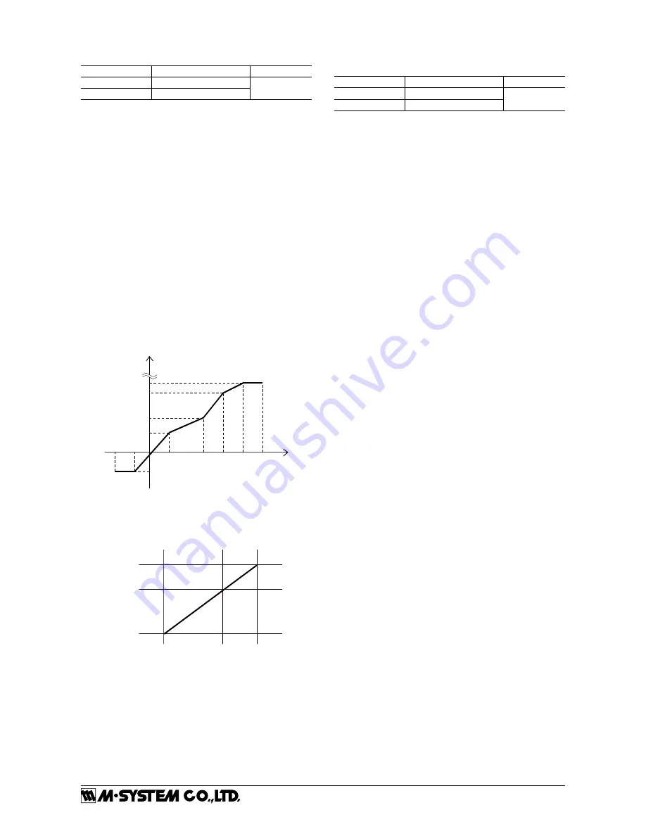
[167 – 388] Table
For the conversion by using user’s table, conversion input
is searched from the table in which X corresponds to input
(unit: %) and Y corresponds to output (unit: %) are paired,
and Y, which corresponds output of matched table, is the
output.
The range is available between -5 to +105 (%) for both X and
Y. For X, it is required to set in ascending order from X001.
Be sure that if it is set with other than ascending order, cor-
rect conversion is not carried out.
Initial value: X001 -5.00
Y001 -5.00
X002 105.00
Y002 105.00
E.g. Setting ascending order
X001
105%
105%
-5%
Y005
Input %
Output %
Y004
Y003
Y002
Y001
-5%
X003
X002
X004 X005
When the input is not defined in the user’s table, two near-
est value for each positive and negative are selected in writ-
ten X. These two data are linearly interpolated and Y is
obtained and output it.
Xn
Xn+1
Yn
Yn+1
Input %
Output %
[01] Lockout Setting
Set Lock / Unlock of lockout setting.
SETTING VALUE DESCRIPTION
INITIAL VALUE
Lock
Lockout setting enable
Lock
Unlock
Lockout setting disable
Even when setting is ‘Lock’, it is available to move on to
each setting mode and confirm the setting value of each
setting parameter. In each setting parameter display, when
‘Lock’, ‘DATA (Locked)’ is indicated, when ‘Unlock’, ‘DATA’
is indicated.


