LYD Technology CM219 Manual Download Page 4


4


6. Please make sure the Camera Power Adapter is well connected and the Receiver is well connected with the Monitor.   


V. Operation Instruction


1. Power On Instruction 

Please connected the Receiver with the Monitor, and plug in the power adapter of the receiver, then you can view the following 

image on the monitor.  
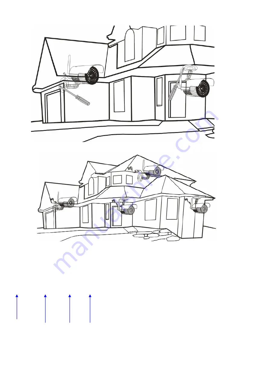
 

  1             2           3         4 

                                                                     1: Signal Bar 

                                                                     2. Wireless Camera Indication 


                                                                     3. FPS of wireless transmission 

                                                                     4. TV System Indication. 

Summary of Contents for CM219

Page 1: ...eatures Digital Wireless Kit 100 Secure Private Communication and Interference Free Work with 4 Cameras maximum One Channel View or Quad View Alarm alert When Signal Dropout AV Output VGA 30 frame NTSC 25 frame PAL Support DVR Connection for Recording 130m Outdoor 40m Indoor Transmission II Product Accessories Introduction 1 Camera Bracket Included 1pc Support 4pcs Maximum 2 Power Adapters 2pcs DC...

Page 2: ...the Camera 8 Antenna of the wireless receiver 9 Channel Switching Button Click for Channel Switching from Cam1 to Cam2 Cam3 Cam4 and Quad Image View Press the Channel Switching Button for 3 seconds for Code Pairing over this channel 10 TV System NTSC PAL Switching Hole It is used for switching the TV system of the Camera kit Because TV systems are various from each country you may need to set the ...

Page 3: ...rs for the camera and receiver and connect the AV cable between the receiver and the monitor Then pair the code of the camera and receiver to display the real time image on the monitor As shown below Please refer to Code Matching Instructions in Operation Instruction 3 5 After the Code Pairing is done disconnect the power adapter of the camera and install the camera anywhere you like You may need ...

Page 4: ...he Monitor V Operation Instruction 1 Power On Instruction Please connected the Receiver with the Monitor and plug in the power adapter of the receiver then you can view the following image on the monitor 1 2 3 4 1 Signal Bar 2 Wireless Camera Indication 3 FPS of wireless transmission 4 TV System Indication ...

Page 5: ...of the wireless camera kit to get a clear image NTSC 制 PAL 制 3 Code Matching Instruction 1 Click the Channel Switching Button and Switch the Channel to Camera 1 and then press the Channel Switching Button for 3 seconds then you will see the code matching notification on the monitor Shown as below 2 Press the Pair Key of the camera within 30 seconds Shown as below ...

Page 6: ...to view the image after the code pairing process is successfully done Shown as below 4 Use the Same Method to complete the code pairing for Camera 2 Camera 3 or Camera 4 If you have 4 Image Display Switching After the code pairing process is completed you can switch the viewing image by click the channel switching button from Cam1 Cam2 Cam3 Cam4 and Quad View As shown below ...

Page 7: ...maging Sensor Type CMOS Picture Total Pixels 640 480pxl NTSC Minimum Illumination 0lux IR on Night Vision Distance 10m Lens 6 0mm View Angle 50 Consumption Current Max Max850mA Power Supply 5V DC Dimensions W D H 95mm 122MM 122MM with antenna Weight 0 45kg Receiver Display Feature Single QUAD Display Resolution Supported VGA 640 480 NTSC 30Frame rate PAL 25Frame rate Receiving Sensitivity 81dbm Co...

Page 8: ...se operating instructions carefully to know the functions clearly It will make you use it conveniently 2 This product is designed for Home and Office Surveillance any illegal operations are not allowed 3 Do NOT remove the shell and housing of power adapter of the product in case of the electric shock 4 The front cover of the camera is made of glass please use it with care and place it out of the r...

Page 9: ...9 ...

Reviews: