


IO-360-N1A Engine Installation and Operation Manual
Requirements for Engine Installation
© 2016 Avco Corporation. All Rights Reserved
Page 14
February 2016
Step 2. Supply Interface Items
1.
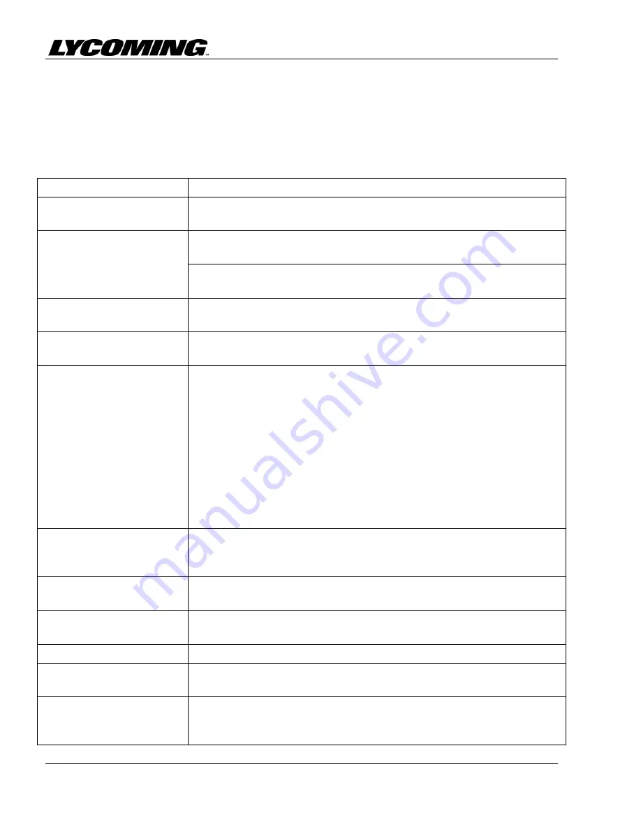
Table 2 contains available equipment options, recommendations and requirements for the
airframe manufacturer to prepare for engine installation.
Table 2
Optional Equipment, Recommendations,
and Requirements to Prepare the Engine for Installation
Issue
Recommendation/Requirement
Installation drawings and
wiring diagrams
Installation drawings are available for purchase from Lycoming
Engines. Refer to Appendix B.
Magnetos
Refer to the magneto manufacturer's documentation for information on
various vibrator and switching arrangements.
If different magnetos, other than those identified in Appendix A, are
necessary refer to the latest revision of Service Instruction No. SI-1443.
Alternators
If a different alternator is necessary, refer to the latest revision of
Service Instruction No. SI-1154.
Cylinder head temperature
measurement
Airframe manufacturer-supplied bayonet thermocouples with AN-4076
fittings for installation on each cylinder head.
Oil Cooler
Provision is made for aircraft manufacturer-supplied full flow oil cooler.
Oil flow through the cooler system will be approximately 7.5 gallons
per minute (28.4 liters minute) and heat rejection will not exceed 820
Btu per minute. The oil cooler must withstand continuous pressure of
150 psi (1034 kPa) and have a minimum proof pressure of 400 psi (2758
kPa). A thermostatic bypass valve and pressure relief valve are optional.
The pressure relief valve limits the pressure drop between cooler
connections to 35 psi (241 kPa). The valve closes at 185ºF (85ºC)
routing all engine oil flow through the cooler. If pressure drop across the
oil cooler system is more than +75 psi (517 kPa) ±15 psi (103 kPa), the
pressure relief valve opens to bypass the cooler.
Oil pressure gage
There is a provision for installation by the aircraft manufacturer for
installation of an oil pressure gage connection (refer to the installation
drawing referenced in Appendix B.)
Fuel supply hose
Correctly-sized hose for the fuel pump supply and return vent line back
to the airframe.
Propeller Shaft
Conforms to specification AS127, Type 2 (Refer to the Installation
Drawing identified in Appendix B.)
Mounting
Rear Type 1 dynafocal mounting – four mounting bosses
Air cleaner
Air cleaner at rated power is 1150 lb of air per hour; pressure drop not to
exceed 6 in. of water.
Exhaust collector
There is a provision for the airframer to install an exhaust collector.
Stainless steel or low carbon steel-type exhaust flanges are available as
optional equipment.