


SECTION 5
LYCOMING OPERATOR’S MANUAL
MAINTENANCE PROCEDURES
O-360 AND ASSOCIATED MODELS
a. Removal of Cylinder Assembly.
(1) Remove exhaust manifold.
(2) Remove rocker box drain tube, intake pipe, baffle and any clips that might interfere with the
removal of the cylinder.
(3) Disconnect ignition cables and remove the bottom sparkplug.
(4) Remove rocker boxcover and rotate crankshaft until piston is approximately at top center of the
compression stroke. This is indicated by a positive pressure inside of cylinder tending to push
thumb off of bottom sparkplug hole.
(5) Slide valve rocker shafts from cylinder head and remove the valve rockers. Valve rocker shafts
can be removed when the cylinder is removed from the engine. Remove rotator cap from exhaust
valve stem.
(6) Remove push rods by grasping ball end and pulling rod out of shroud tube. Detach shroud tube
spring and lockplate and pull shroud tubes through holes in cylinder head.
NOTE
The hydraulic tappets, push rods, rocker arms and valves must be assembled in the same
location from which they were removed.
(7) Remove cylinder base nuts and hold down plates (where employed) then remove cylinder by
pulling directly away from crankcase. Be careful not to allow the piston to drop against the
crankcase, as the piston leaves the cylinder.
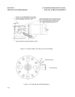
b. Removal of Piston from Connecting Rod –
Remove the piston pin plugs. Insert piston pin puller
through piston pin, assemble puller nut;then proceed to remove piston pin. Do not allow connecting
rod to rest on the cylinder bore of the crankcase. Support the connecting rod with heavy rubber band,
discarded cylinder base oil ring seal, or any other non-marring method.
c. Removal of Hydraulic Tappet Sockets and Plunger Assemblies –
It will be necessary to remove and
bleed the hydraulic tappet plunger assembly so that dry tappet clearance can be checked when the
cylinder assembly is reinstalled. This is accomplished in the following manner:
(1) Remove the hydraulic tappet push rod socket by inserting the forefinger into the concave end of
the socket and withdrawing. If the socket cannot be removed in this manner, it may be removed
by grasping the edge of the socket with a pair of needle nose pliers. However, care must be
exercised to avoid scratching the socket.
(2) To remove the hydraulic tappet plunger assembly, use the special Lycoming service tool. In the
event the tool is not available, the hydraulic tappet plunger assembly may be removed by a hook
in the end of a short piece of lockwire, inserting the wire so that the hookengages the spring of
the plunger assembly. Draw the plunger assembly out of the tappet body by gently pulling the
wire.
5-6
Summary of Contents for AIO-360 Series
Page 13: ...This Page Intentionally Left Blank ...
Page 15: ...This Page Intentionally Left Blank ...
Page 21: ...This Page Intentionally Left Blank ...
Page 23: ...This Page Intentionally Left Blank ...
Page 35: ...This Page Intentionally Left Blank ...
Page 37: ...This Page Intentionally Left Blank ...
Page 105: ...This Page Intentionally Left Blank ...
Page 107: ...This Page Intentionally Left Blank ...
Page 121: ...This Page Intentionally Left Blank ...
Page 123: ...This Page Intentionally Left Blank ...
Page 131: ...This Page Intentionally Left Blank ...
Page 149: ...This Page Intentionally Left Blank ...
Page 151: ...SECTION 8 LYCOMING OPERATOR S MANUAL TABLES O 360 AND ASSOCIATED MODELS 8 2 ...
Page 152: ...LYCOMING OPERATOR S MANUAL SECTION 8 O 360 AND ASSOCIATED MODELS TABLES 8 3 ...