5 / 12
2
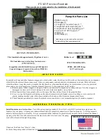
1
2
4
3
Install telescopic mounting poles
Unscrew fastening screw on right lower poles assembly by using E2 (6mm
Allen Wrench) from hardware pouch. Put screw aside. As shown in Fig-1.
Use both hands to grip upper pole right, twist and pull upper pole upward
until your desired height. Then twist upper pole again toward plunger holes
direction and engaged spring ball into the plunger hole and set. Secure screw
firmly as shown in Fig-2.
To re-set height, two people are required. One person to hold up the TV while
the second simply unscrews the 2 x fastening screws on left and right lower
poles by using E2 (6mm Allen Wrench) and put screws aside. Using both
thumbs to depress the 2 spring balls and person holding the TV lower down
or raises up the TV to desired height and let plunger set into holes. Secure 2x
fastening screws firmly. As shown in fig-2.
Repeat step 2 on left pole assembly
Fastening screws
Fastening
screws
Left lower pole
Right lower pole
65 in
63 in
61 in
Spring
plunger
Height label
Left upper pole
Right upper pole
E2
E2
G
G
Summary of Contents for FP4000
Page 4: ...4 12 1 1 4 2 3 Post assembly to base installation G F D2 A2 B2 E2 F F...
Page 6: ...6 12 3 AV Shelf assembly and installation 1 2 3 4 5 Q Q R R R M G Q M N M1x4...
Page 7: ...7 12 4 Installation of interface 1 2 H G J C2x4 E2...
Page 8: ...8 12 5 VESA Mounting patterns...
Page 11: ...11 12 8 Camera tray installation 1 2 3 4 5 L J J L L L K K L1x2 L1x2 L2x2 J1x2 J1x2 L2x2...
Page 12: ...06 09 15 12 12 9 Cable and wires installation 1 2 S G S...