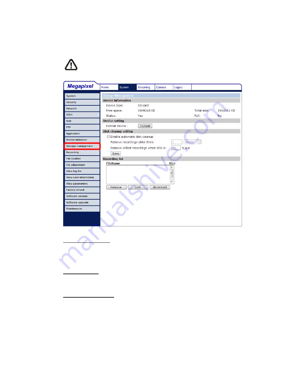
Luxon Video D-MIPC1600 User Manual Download Page 44


43

5.3.9 Storage 

Management 

Users can implement local recording to the Micro SD/SDHC card. 


NOTE:

 Please format the Micro SD/SDHC card first before recording 

starts. 


Device information 

When users insert the Micro SD/SDHC card, the card information such as the 
memory capacity and status will be shown at Device Information section. 
 

Device setting 

Press the “Format” button to format the memory card. 
 

Disk cleanup setting 

Users can enable automatic recordings cleanup by specifying the time and 
storage limits 


Summary of Contents for D-MIPC1600

Page 1: ...D MIPC1600 User Manual Ver1 3...

Page 2: ...3 Network 26 5 3 4 DDNS 31 5 3 5 Mail 32 5 3 6 FTP 33 5 3 7 Application Excluding Compact IP Dome 34 5 3 8 Motion Detection 39 5 3 9 Storage Management 43 5 3 10 Recording 45 5 3 11 File Location 46 5...

Page 3: ...ting 71 5 5 5 Contrast Setting 71 5 5 6 Saturation Setting 71 5 5 7 Hue Setting 72 5 5 8 IR Function 72 5 5 9 TV System Setup 72 5 6 Logout 73 6 CMS Software Introduction 74 Appendix A Technical Speci...

Page 4: ...aming Full HD Real time IP Camera develops superior H 264 to apply for high resolution digital broadcast Attributing to the IP Camera s flexible platform the camera can be applied in various installat...

Page 5: ...MIC IN Two way audio transmission Power LED Power connection indication green light Reset button Reset to factory default AUTO IRIS connector Auto iris lens connector NETWORK with PoE RJ 45 connector...

Page 6: ...5 Dimensions...

Page 7: ...ser Microsoft Internet Explorer 6 0 or later Network Card 10Base T 10 Mbps or 100Base TX 100 Mbps operation Viewer ActiveX control plug in for Microsoft IE 2 2 Installation Please follow the instructi...

Page 8: ...rk switch or PC NOTE In some cases you may need use an Ethernet crossover cable when connecting the IP Camera directly to the PC Check the status of the link indicator and activity indicator LEDs if t...

Page 9: ...and then double click Add or Remove Programs In the Currently installed programs list select DCViewer and click the button Remove to uninstall the existing DC Viewer as shown in the figure below Dele...

Page 10: ...9 STEP 2 Click on Delete then tap the Delete Files in the Temporary Internet files section...

Page 11: ...10 The popup window for confirmation will come out as shown below Click OK to start deleting the files...

Page 12: ...ceSearch exe which can be found in DeviceSearch folder in the supplied CD Device Search Software Setup Step 1 Double click on the program Device Search exe see the icon below its window will appear as...

Page 13: ...n the figure below The IP Camera s default IP address is 192 168 0 250 Step 4 Double click or right click and select Browse to access the camera directly via web browser Step 5 Then the prompt window...

Page 14: ...ly in the device finding list Refer to the following section for changing the IP Camera s network property Example of Changing IP Camera s Network Property Users can directly change an IP Camera s net...

Page 15: ...he Note of setting change Wait for one minute to re search the IP Camera Step 4 Click the Device Search button to search all the devices Then select the IP Camera with the correct MAC address Double c...

Page 16: ...he Information Bar just below the URL bar may come out and ask for permission to install the ActiveX Control for displaying video in browser see the figure below Right click on the Information Bar and...

Page 17: ...on who can configure the IP Camera and authorize users access to the camera User refers to whoever has access to the camera with limited authority i e entering Home and Camera setting pages Image and...

Page 18: ...hapter information about main page introduction system related settings and camera settings will be described in detail For further information about CMS software please refer to 6 CMS Software Introd...

Page 19: ...ngs etc Further details will be interpreted in section 5 3 System Related Settings Streaming setting The administrator can modify video resolution and rotate type and select audio compression mode in...

Page 20: ...n the camera model Screen Size Adjustment Image display size can be adjusted to x1 2 and full screen Digital Zoom Control In the full screen mode users can implement digital PTZ by rotating the mouse...

Page 21: ...pshots will automatically be saved in the appointed place The default place of saving snapshots is C To change the storage location please refer to section 5 3 11 File Location for further details Vid...

Page 22: ...Settings The figure below shows all categories under the System tab Each category in the left column will be explained in the following sections NOTE The System configuration page is only accessible...

Page 23: ...FTP the host name entered here will display in the alarm message Time Zone Select the time zone you are in from the drop down menu Sync With Computer Time To enable DST please check the item and then...

Page 24: ...d Then select an update interval from the drop down menu For further information about NTP please see the web site www ntp org 5 3 2 Security Click the category Security and the page is shown as the f...

Page 25: ...tem allows the appointed User to change camera parameters on the Camera Setting page Talk Listen Talk and Listen functions allow the appointed user in the local site PC site communicating with for ins...

Page 26: ...25...

Page 27: ...tomatically DHCP The camera s default setting is Use fixed IP address Please refer to the previous section 4 Accessing Camera for login with the default IP address If select Get IP address automatical...

Page 28: ...ank and change the setting ex 192 168 7 254 Press Save to confirm the new setting When using static IP address to login to the IP Camera users can access it either through DeviceSearch software see 4...

Page 29: ...on the Save button to complete the setting Advanced Web Server port The default web server port is 80 Once the port is changed the user must be notified the change for the connection to be successful...

Page 30: ...nP Setting Enable UPnP When the UPnP is enable whenever the IP Camera is presented to the LAN the icon of the connected IP Cameras will appear in My Network Places to allow for direct access as shown...

Page 31: ...for UPnP component installation procedure Enable UPnP port forwarding When the UPnP port forwarding is enabled the IP Camera is allowed to open the web server port on the router automatically NOTE To...

Page 32: ...e using a dynamic IP address to be associated to a static domain name so others can connect to it by name Enable DDNS Check the item to enable DDNS Provider Select one DDNS host from the provider list...

Page 33: ...r sending e mail messages between servers SMTP is a relatively simple text based protocol where one or more recipients of a message are specified and the message text is transferred The configuration...

Page 34: ...File Transfer Protocol FTP site when motion is detected Users can assign alarm message to up to two FTP sites The FTP setting page is shown below Enter the FTP details which include server server por...

Page 35: ...events images Refer to alarm pin definition below to connect alarm devices to the IP Camera if needed The alarm configuration page is also shown below Alarm Pin Definition 1 Output 2 Output 3 Input 4...

Page 36: ...s are listed as follows Enable Alarm Output Select the item to enable alarm relay output Send Alarm Message by FTP E Mail The Administrator can select whether to send an alarm message by FTP and or E...

Page 37: ...m and the alarm triggered recording will be saved into your Micro SD card NOTE Please make sure the local recording with Micro SD SDHC card is activated so that this function can be implemented See se...

Page 38: ...d e mail address NOTE Make sure SMTP or FTP configuration has been completed See section 5 3 5 Mail and 5 3 6 FTP for further details File Name Enter a file name in the blank ex image jpg The uploaded...

Page 39: ...suffix will end at the number being set For example if the setting is up to 10 the file name will start from 00 end at 10 and then start all over again Overwrite The original image in the FTP site wil...

Page 40: ...The Motion Detection Window is for defining the motion detection area To change the size of the Motion Detection Window move the mouse cursor to the edge of the frame and draw it outward inward Movin...

Page 41: ...Detection You will be able to turn on off Motion Detection in System section Default setting is Off Motion Detection Setting Users could adjust various parameters of Motion Detection in this section S...

Page 42: ...efined type of alarm output to enable alarm relay output when motion is detected NOTE This option is excluded in the Compact IP Dome Camera Record stream to SD Card Select this item and the Motion Det...

Page 43: ...ent images will be sent to the appointed e mail address NOTE Make sure SMTP or FTP configuration has been completed See section 5 3 5 Mail and 5 3 6 FTP for further details File Name The uploaded imag...

Page 44: ...ding starts Device information When users insert the Micro SD SDHC card the card information such as the memory capacity and status will be shown at Device Information section Device setting Press the...

Page 45: ...name and date order NOTE The capital letter A M R appears in the very beginning of name denotes the sort of the recording A stands for Alarm M stands for Motion R stands for regular recording Download...

Page 46: ...Recording Two types of schedule mode are offered Always and Time Frame setting Users can setup the time frame to fit the recording schedule or choose Always to activate Micro SD SDHC Card Recording al...

Page 47: ...napshots and live video recording The default setting is C Once confirm the setting press Save and all the snapshots and recording will be saved in the designate location NOTE Please make sure the sel...

Page 48: ...12 Iris Adjustment Excluding Compact IP Dome For users who use Auto iris lens when it is required to implement iris adjustment please refer to the Iris adjustment procedure in the setting page to adju...

Page 49: ...48 5 3 13 View Log File Click on the link to view the system log file The content of the file provides useful information about configuration and connections after system boot up...

Page 50: ...gin information and privileges see 5 3 2 Security View User Login Information All the users in the network will be listed in the User information zone as shown below As the figure below shows User 432...

Page 51: ...page and the Administrator can view each user s privileges As the figure above shows User 1 1 0 1 1 1 0 1 I O access Camera control Talk Listen see 6 3 2 Security Therefore it denotes the user is gran...

Page 52: ...51 5 3 15 View Parameters Click on this item to view the entire system s parameter setting...

Page 53: ...P Camera to factory default setting if needed Set Default Click on the Set Default button to recall the factory default settings Then the system will restart in 30 seconds NOTE The IP address will be...

Page 54: ...53 5 3 17 Software Version The current software version is displayed in the software version page which is shown as the figure below...

Page 55: ...Software upgrade can be carried out in the Software Upgrade page as shown below NOTE Make sure the upgrade software file is available before carrying out software upgrade The procedure of software upg...

Page 56: ...Step 2 Pull down the upgrade binary file list and select the file you want to upgrade in this case select userland jffs2 Step 3 Press Upgrade The system will first check whether the upgrade file exis...

Page 57: ...rowser Step 5 Click Control Panel and then double click Add or Remove Programs In the Currently install programs list select DCViewer and click the button Remove to uninstall the existing DC Viewer St...

Page 58: ...ng configuration file to the IP Camera Export Users can save the system settings by exporting the configuration file bin to a specified location for future use Press the Export button and the popup Fi...

Page 59: ...Press the tab Streaming in the top of the page and the configurable video and audio items will display in the left column In Streaming the Administrator can configure specific video resolution video c...

Page 60: ...Output is only available for Box Camera and Vandal Proof Dome Text Overlay Settings Users can select the items to display data including date time text on the live video pane The maximum length of the...

Page 61: ...vertically Mirror If select Mirror the image will be rotated horizontally 180 Degree Selecting 180 Degree will make the image 180 counter clockwise inversed Click Save to confirm the setting GOV Sett...

Page 62: ...lect a proper MJPEG H 264 compression mode in the video compression page see the figure below depending on the application Users can also decide whether to display compression information on the Home...

Page 63: ...CBR Mode Setting The CBR Constant Bit Rate mode could be the preferred bit rage mode if the bandwidth available is limited It is important to take account of image quality while choosing to use CBR mo...

Page 64: ...working users can select the Multicast mode The page is shown as follows Video OCX protocol setting options include RTP over UDP RTP over RTSP TCP RTSP over HTTP MJPEG over HTTP Select a mode accordin...

Page 65: ...if necessary The setting page is shown as below Video Frame Skip options include No skipping default Frame skipping at 5 frame internal Frame skipping at 10 frame internal Frame skipping to 15 frame i...

Page 66: ...adjust the mask s size and place it on the target zone NOTE It is suggested to set the Video Mask twice bigger than the object Cancel a Mask Uncheck the checkbox of the Video Mask meant to be deleted...

Page 67: ...the Administrator can select one transmission mode and audio bit rate Transmission Mode Full duplex Talk and Listen simultaneously In the Full duplex mode the local and remote sites can communicate w...

Page 68: ...ex mode the local remote site can only listen to the other site Disable Select the item to turn off the audio transmission function Server Gain Setting Set the audio input output gain levels for sound...

Page 69: ...ttings The figure below is the camera configuration page Details of each parameter setting are described in the following subsections NOTE Camera settings and function buttons will vary depending on t...

Page 70: ...hutter Speed IRIS and AGC Auto Gain Control control circuits work together automatically to get consistent video output level The shutter speed range is from 1 to 1 8 sec with 4 options Users could se...

Page 71: ...e Balance Control modes according to the operating environment The following table shows the color temperature of some light sources for reference Light Sources Color Temperature in K Cloudy Sky 6 000...

Page 72: ...rease video brightness select a bigger number Press SET to confirm the new setting 5 5 4 Sharpness Setting Increasing the sharpness level can make the image looked sharper especially enhance the objec...

Page 73: ...to 13 Press SET to confirm the new setting 5 5 8 IR Function With the IR cut filter the Dome Camera can still catch clear image at night time or in low light conditions Press SET to confirm the new s...

Page 74: ...73 5 6 Logout Press the tab Logout in the top of the page and the login window will pop up This enables login with another user name...

Page 75: ...s HD 25 30 fps Full HD 15 fps Brightness Manual Exposure Auto Manual Sharpness Manual Contrast Manual White Balance Auto Manual Saturation Manual Hue Manual Digital Zoom Support Motion detection On Of...

Page 76: ...Iris optional DC Drive Analog Video optional 1 0 Vp p 75 BNC LED Indicator Power Link ACT General Operating Temperature 0 C 50 C Humidity 10 to 90 No Condensation Power Source DC 12V PoE Power Consum...

Page 77: ...her set Internet security level to default or change ActiveX controls and plug ins settings Internet Security Level Default Step 1 Start the Internet Explorer IE Step 2 Select Tools from the main menu...

Page 78: ...m the setting Close the browser window and open a new one later when accessing the IP Camera ActiveX Controls and Plug ins Settings Step 1 3 Refer to the previous section above Step 4 Down the page pr...

Page 79: ...and scrip behaviors 3 Download signed ActiveX controls 4 Download using ActiveX controls 5 Initialize and script ActiveX not marked as safe 6 Run ActiveX controls and plug ins 7 Script ActiveX control...

Page 80: ...Procedure The procedure of DC Viewer software download is specified as follows Step 1 In the DC Viewer installation page click Next for starting installing Step 2 Setup starts Please wait for a while...

Page 81: ...1 Step 3 Click Finish to close the DC Viewer installation page Then the IP Camera s Home page will display as follows NOTE Please note that the function buttons will vary depending on the camera model...

Page 82: ...the camera on a stable mount with the test chart or object at least 75 feet 23 meters away or as far as possible Step 2 Make sure the iris is wide open Therefore it is advised to keep the environment...

Page 83: ...ts Please follow the instructions below to install UPnP components Step 1 Go to Start click on Control Panel and then double click Add or Remove Programs Step 2 Click on Add Remove Windows Components...

Page 84: ...elect Networking Services from the Components list in the Windows Components Wizard window and then click Details Step 4 Select UPnP User Interface in the Networking Services subcomponents list and th...

Page 85: ...85 Step 5 Click Next in the Windows Components Wizard page Step 6 Click Finish to complete installation...

Reviews: