D.3.3. Installation
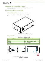
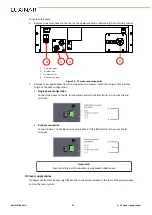
INTERFACE
Umax-SET
- +
VOLTAGE-SENSE
OUTPUT-
L1 L2 L3
MAINS INPUT
Water in
Water out
1
2
3
4
5
1
15-pin D-type auxiliary interface connector
2
Voltage sense connector
3
DC output connectors
4
Coolant connectors
5
Three-phase mains supply connector
Figure 38 - Rear panel connections
Mains AC power connections
Important!
Under certain conditions, it may be possible for high voltage and current cables to emit noise
energy levels that may interfere with control signal cables. To eliminate the possibility of
interference, cables carrying control signals should be routed along a different path to power
cables.
The power supply is provided with a mains supply cable. If this cable needs to be replaced with a
longer cable, ensure the replacement cable is of the correct rating for the power supply.
DANGER
Risk of electric shock or severe damage to the equipment
Ensure that the equipment is disconnected from the mains supply before making this
connection.
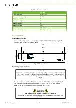
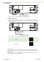
Connect the three-phase cable to the L1, L2 and L3 terminals on the rear panel of the power supply.
Connect the earth wire to the earth terminal.
L3
L2
L1
Figure 39 - Three-phase mains supply connection
D. DC power supply options
62
906-0227-00 REV 1
Summary of Contents for SR 10 AOM
Page 1: ...USER MANUAL SR AOM series Sealed CO2 laser sources with integrated AOM...
Page 8: ...Preface iv 906 0227 00 REV 1...
Page 40: ...6 Installation 32 906 0227 00 REV 1...
Page 42: ...7 Transport and recommissioning 34 906 0227 00 REV 1...
Page 52: ...8 Interfacing 44 906 0227 00 REV 1...


