9
GB
3. Starting up
3.1 Assembly in the container
Fasten the pump in the container with appropriate drum ad-
apters. Make sure that the container with the installed pump
is enough stably even in empty condition. This is of special
attention with small containers.
3.2 Mains connection
It is recommended to provide the motor with a protection switch
corresponding to the power consumption so as to prevent motor
destruction by overloading.
The electrical connection may only be carried out by
trained qualified personnel. Following regulations must
be observed:
- All works must only be carried out in voltage-free condition
of the motor.
If available, set the protection switch mounted to OFF.
- Mains voltage and frequency are as specified on the rating
plate.
- Dimension of the connecting cable must be adjusted to the
nominal current.
- The insulation of the connecting cable must be adjusted to
the environmental conditions.
3.3 Checking the direction of rotation
After the motor has been started, the direction of rotation of
the drive shaft must correspond to the rotation arrow on the
rating plate. If necessary, the motor terminal connections must
be reversed.
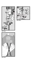
3.4 Connection to the pump tube
The motor is mounted on the pump tube. The upper cou-
pling
(Fig. 1 - Pos.1)
on the motor engaging in the coupling
(Fig. 1 - Pos. 2
) of the pump tube. The motor and pump
tube are then firmly connected by means of the handwheel
(right-hand thread).
When using plastic pump tubes, it is recommended to relieve
the pump tube of the motor weight by means of a support.
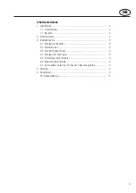
3.5 Mounting the vent valve
Before starting up the pump, replace screw plug
(Fig. 2 –
Pos. 1)
by vent valve
(Fig. 2 – Pos. 2)
. Thereafter, the motor
may no more be operated or stored in horizontal or inclined
position
≥
15° as oil will otherwise leak.
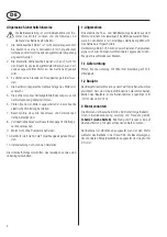
3.6 Maximum immersion depth
Care must be taken to ensure that the pump is not submerged
further than its discharge port
(see Fig. 3)
.
3.7 Uncontrolled re-start of the pump after
voltage drop
The motor is not equipped with a low voltage release.
After a voltage drop the pump may re-start
uncontrolled!
4. Maintenance
After 500 working hours:
Check gear oil level by means of an oil sight-glass situated
above the rating plate.
In case of oil deficiency, top up gear oil ESSO HDX or equivalent
oil HD SAE 20.
After 1000 working hours:
Change gear oil. Use 0.2 l gear oil ESSO HDX or equivalent
oil HD SAE 20.
Protect the environment: Handling and waste disposal of
mineral oils are subject to statutory provisions. Deliver waste
oil to an authorized point of acceptance.
5. Repairs
Repairs should only be made by the manufacturer or authorized
Lutz-dealers. Only use genuine Lutz spare parts.

