


2
Installation
1.
Disconnect power to the keypads by turning off all
circuit breakers connected to the HomeWorks
®
Processor or keypad link auxiliary power supply.
Danger -
Wiring with power ON may result in
personal injury.
2.
Address keypads.
Assign a unique address to
each keypad using the DIP switch on the back of
the keypad. See Figure 2 (page 3) for DIP switch
location. See Figure 3 (page 4) for DIP switch set-
tings. Be sure to record the address for future pro-
gramming purposes.
3.
Strip insulation from wires to 3/8" (10mm). Each
terminal will accept one or two 18-gauge (1.0mm
2
)
wires.
4.
Unplug terminal block from the keypad circuit
board.
5.
Connect wiring to terminal block as shown in
Figures 1 and 2 (page 3).
6.
Plug the keypad terminal block back onto the cir-
cuit board. Be sure to orient the terminal block
correctly.
7.
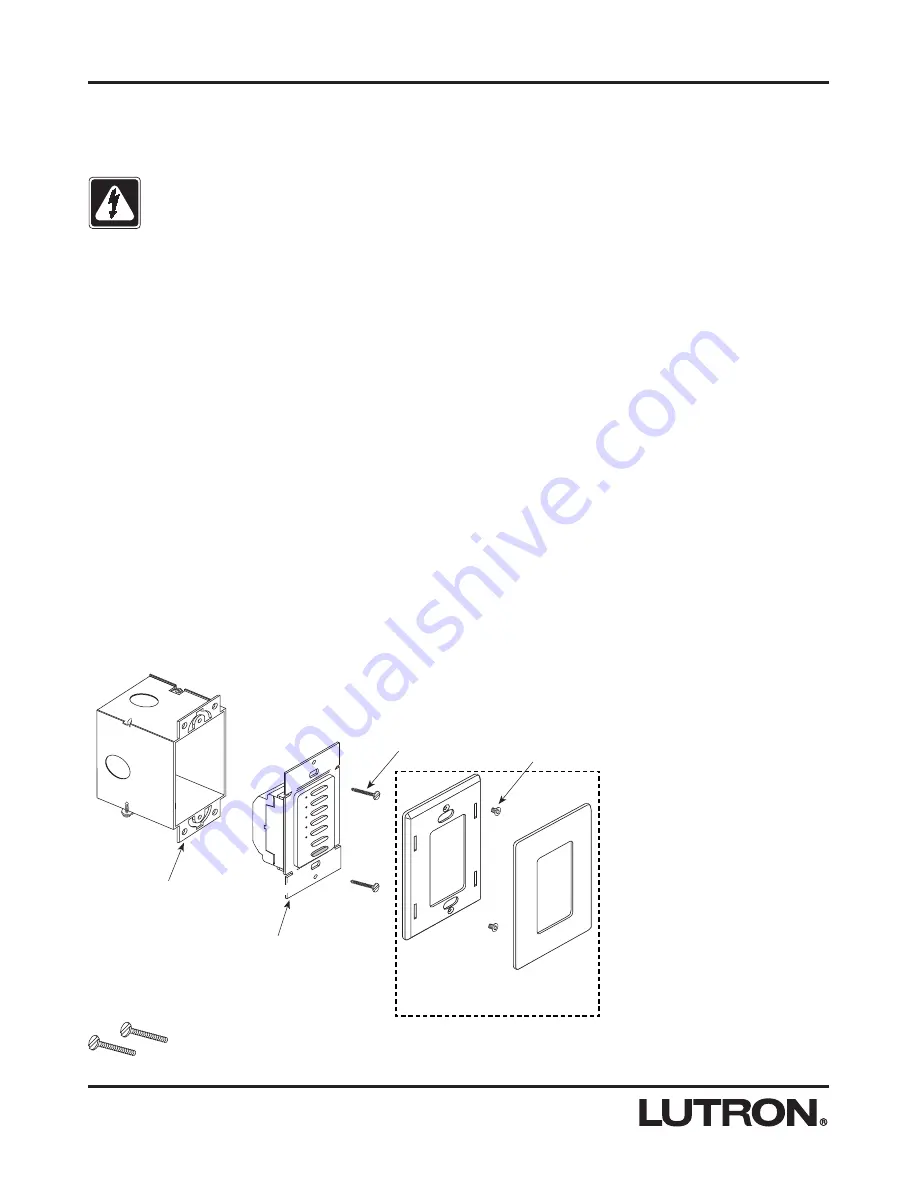
Mount keypad as shown in Figure 4 (page 4).
Do
not over-tighten mounting screws.
8.
Restore power to the
HomeWorks
Processor or
keypad link auxiliary power supply.
Mounting Diagram
Wallbox
Keypad
Mounting
Screws
Keypad
Adapter
Mounting
Screws
Wallplate and Adapter are purchased separately.
Included:
Mounting Screws (2)