3-16
CDD3000-HF Operation Manual
3 Installation
3.5
Braking resistor
(RB)
During regenerative operation, e.g. when applying the brake to the drive,
the motor returns energy to the CDD3000-HF drive controller. This
increases the voltage in the DC-link. If the voltage exceeds a threshold
value, the internal braking transistor is activated and the regenerated
power is converted into heat by way of a braking resistor.
The switching transistor is installed as standard. The design of the
external braking resistor depends on a number of drive factors:
for example the load to be moved, the required dynamics of the drive or
the braking and cycle duration.
Note:
The design of the braking resistor must be clarified at the
project planning stage. Please talk to us!
Attention: In device version
CDD3x.xxx-HF, Wx.x,
BR
the braking resistor is built-in. No additional braking resistor
may be connected to terminals X1/L+ and RB; this would
damage the CDD3000-HF drive controller.
Attention: Braking the drive is important to the safety of the
machine or system!
Commissioning should include a test for safe functioning of
the braking system! Incorrect dimensioning (overload) could
lead to destruction of the braking resistor or the braking
electronics, and damage to the machine or system. Overload
(failure of the braking device) can also lead to serious or fatal
physical injury to human beings, for example in lifting
applications!
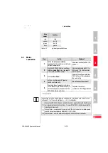
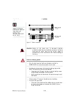
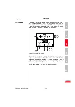
Figure 3.8 Braking resistor connection
X1
L+
RB
RB


