4. Start the LSProbe TCP Server via the Windows
Start Menu and check that the green power
LED is constantly on. The LSProbe TCP Server
will display a list of detected calibration data
sets and a list of all detected Computer Inter-
faces as shown above.
If this step fails, consult the LSProbe User’s
Manual, Section 4.2.
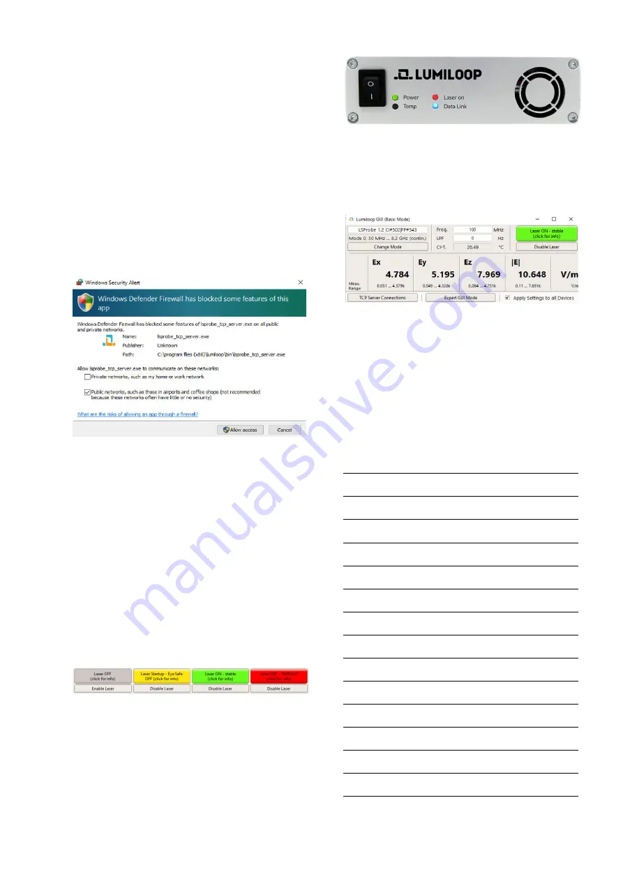
5. Since the LSProbe TCP Server needs to open
a TCP port, the system’s firewall may ask for
permission for network access. Access must
be granted as shown below in order to run the
LSProbe TCP Server, the default TCP port num-
ber is 10,000.
5
LUMILOOP GUI Operation
1. Start the LUMILOOP GUI via the Windows
Start Menu.
2. Click the “Enable Laser” button to activate the
supply laser and turn the E-Field Probe on. The
Computer Interface’s orange “Laser on” indica-
tor LED will show the activity of the supply
laser.
Warning: When the orange LED is flashing,
Automatic Power Reduction (APR) is disabled.
Interrupting optical connections is dangerous!
The GUI indicates proper operation by display-
ing a green “Laser Status” indicator as shown
above.
Stable operation is indicated by the
Computer Interface’s continuously on “Power”,
“Laser on” and “Data Link” LEDs as shown be-
low.
3. As shown below, the E-field strength values
for x, y, z components and the isotropic field
strength are displayed by the GUI, maximum
and minimum calibrated field strength for the
set mode and frequency are displayed below.
4. For accurate E-field strength measurements the
field’s frequency must be specified using the
“Freq./Hz” input field. Values are entered in
Hertz, SI unit prefixes may be used, e.g. “1G”
for 1 GHz, as shown above.
5. For advanced features use the “Expert GUI
Mode” radio button.
Personal Notes:


