background image


English -  3

Chapter 1 Safety Instructions 

Always follow these safety instructions when setting up and using the Ceiling Camera: 

1.  Use attachments only as recommended. 
2.  Use the type of power source indicated on the Ceiling Camera. If you are not sure of the type of power available, 

consult your distributor or local electricity company for advice. 

3.  Always take the following precautions when handling the plug. Failure to do so may result in sparks or fire. 


Ensure the plug is free of dust before inserting it into a socket. 


Ensure that the plug is inserted into the socket securely. 

4.  Do not overload wall sockets, extensions leads or multi-way plug boards as this may cause fire or electric shock. 
5.  Do not place the Ceiling Camera where the cord can be stepped on as this may result in fraying or damage to the 

lead or the plug. 

6.  Do not block the slots and openings in the Ceiling Camera case. They provide ventilation and prevent the Ceiling 

Camera from overheating. Do not place the Ceiling Camera on the soft surface of sofas, carpets or others. 

7.  Never push any kind of objects through cabinet slots. Never allow any kind of liquid to spill into the Ceiling Camera. 
8.  Except as specifically instructed in this User Manual, do not attempt to operate this product by yourself. Opening or 

removing covers may expose you to dangerous voltages and other hazards. Refer all servicing to licensed service 
personnel. 

9.  Unplug the Ceiling Camera during thunderstorms or if it is not going to be used for an extended period. Do not 

place the Ceiling Camera or remote control on top of heat-emitting equipment or heated objects such as a car, etc. 

10.  Unplug the Ceiling Camera from the wall outlet and refer serving to licensed service personnel when the following 

situations happen: 


If the power cable or plug becomes damaged or frayed. 


If liquid is spilled into it or the Ceiling Camera has been exposed to rain or water. 

11.  Due to safety concerns, please make sure the ceiling mounting which you purchased complies with UL and VESA 

standard. And it’s highly recommended to have the technical persons who are certified by local agents to apply 
installation and replacement. 

<Note> Using an incorrect battery type in the remote control may result in breakdown. Follow your country’s 
instructions on how to dispose of used batteries.
 

  Precautions 

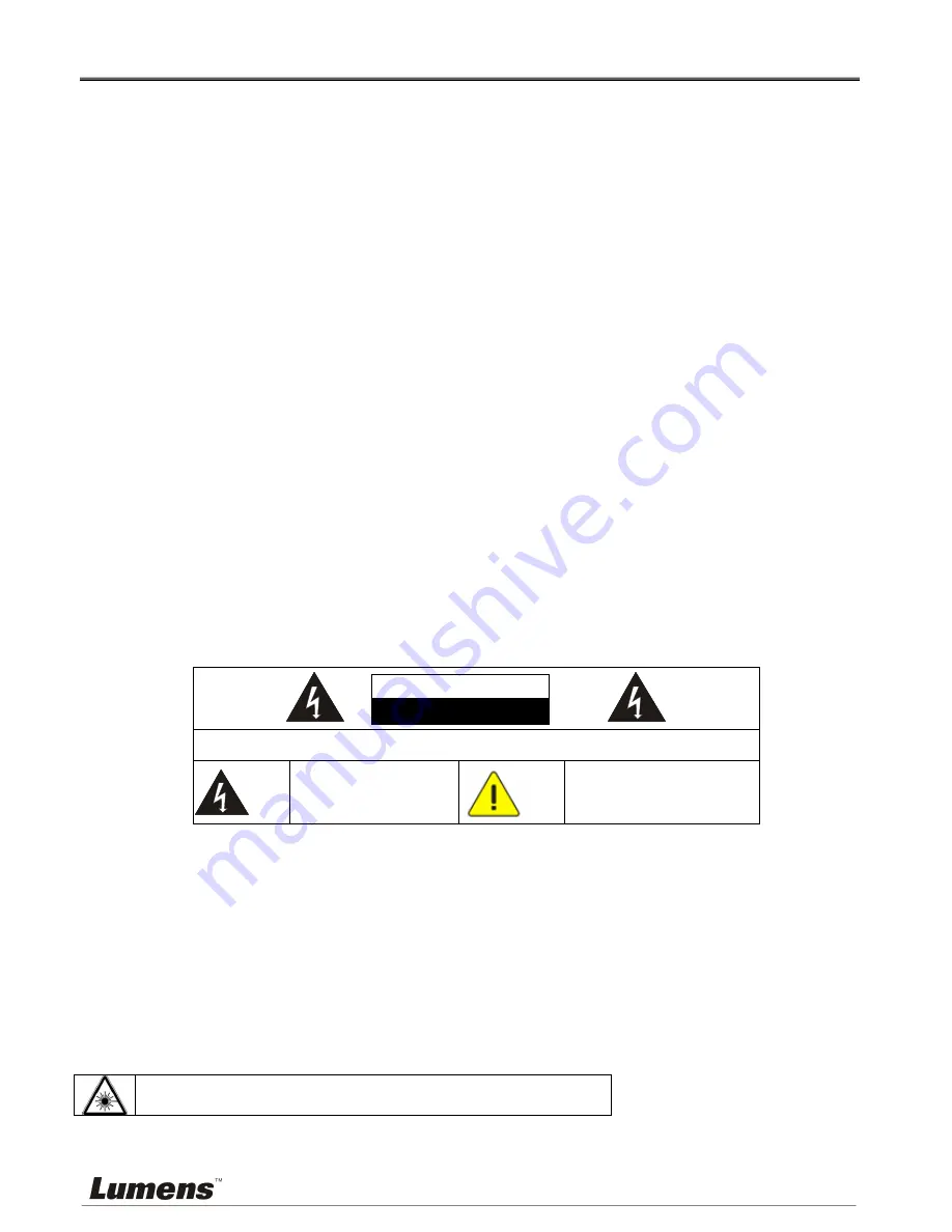
Warning: To reduce the risk of fire or electric shock, do not expose this appliance to rain or moisture. 

If the Ceiling Camera will not be used for an extended time, unplug it from the power socket. 


Caution: To reduce the risk of electric shock, do not remove cover (or back). No user-serviceable 
parts inside. Refer servicing to licensed service Personnel. 


This symbol indicates that 
this equipment may contain 
dangerous voltage which 
could cause electric shock. 


This symbol indicates that there 
are important operating and 
maintenance instructions in this 
User Manual with this unit. 

  FCC Warning 

This Ceiling Camera has been tested and found to comply with the limits for a Class A digital device, pursuant to Article 
15-J of FCC Rules. These limits are designed to provide reasonable protection against harmful interference in a 
residential installation. 

  FDA Warning 

This Devise Complies with DHHS Radiation Rules, 21CFR Chapter 1, Subchapter J. 

  EN55022 (CE Radiation) Warning 

This product is intended for use in a commercial, industrial, or educational environment. It is not intended for residential 
use. 

This is a Class A product. In a residential environment it may cause radio interference, in which case the user may be 
required to take adequate measures. The typical use is in a conference room, meeting room or auditorium. 

  EN60825 (Laser) Warning 


Laser Radiation Do Not Stare Into Beam Class 2 Laser Product 

  Caution 

Danger of explosion if battery is incorrectly replaced. Replace only with same or equivalent type. Dispose batteries according to 
manufacture’s instructions. 

Note 

Risk of Electric Shock 


Summary of Contents for CL510

Page 1: ...CL510 Document Camera Installation Guide Version V06 Date 2015 05 07 ...

Page 2: ... 2 Package Contents 4 Chapter 3 Product Description 5 3 1 Body size 5 3 2 IO description 7 Chapter 4 Installation and Connections 8 4 1 Preparation before installation 8 4 2 Switch setting 10 4 3 System diagram 11 4 4 Set up the power frequency 11 4 5 Set the position of the object to be captured Laser mark 11 4 6 AF Table Set for auto focus setting 12 Chapter 5 Troubleshooting 14 Attachment 1 15 ...

Page 3: ...ct Lumens Digital Optics Inc hereby reserves the right to make changes to product specifications without prior notice The information in this file is subject to change without prior notice To fully explain or describe how this product should be used this manual may refer to names of other products or companies nevertheless without any intention of infringement Disclaimer of warranties Lumens Digit...

Page 4: ...he Ceiling Camera has been exposed to rain or water 11 Due to safety concerns please make sure the ceiling mounting which you purchased complies with UL and VESA standard And it s highly recommended to have the technical persons who are certified by local agents to apply installation and replacement Note Using an incorrect battery type in the remote control may result in breakdown Follow your coun...

Page 5: ...Quick Start Guide Instruction for Installation Remote Control For download of other language versions please visit Lumens website Power Adapter USB Cable VGA Cable IR extender Appearance may vary depending on country region Ceiling Mount Hanger ...

Page 6: ...English 5 Chapter 3 Product Description 3 1 Body size 3 1 1 The size of CL510 is as follows Length 126mm 4 96inch Width 86mm 3 39inch Height 140 9mm 5 55inch ...

Page 7: ...English 6 3 1 2 The size of CL510 together with U hanger is as follows Length 126mm 4 96inch Width 86mm 3 39inch Height 220mm 8 66inch ...

Page 8: ...C IN Power input 2 ETHERNET RJ 45 Network cable interface 3 DVI OUT DVI Image out 4 RS232 RS232 Interface 5 VGA OUT VGA Image out 6 IR IR Interface 7 DIP SWITCH DIP Switch setting 8 USB PORT A type USB Port 9 USB PORT B type USB Port ...

Page 9: ...plier for any shortage and make sure to keep the accessories in the box intact 4 1 3 Please choose a proper place for installation of CL510 in advance Please determine an installation place according to the following requirements 4 1 3 1 Confirm the position for the object to be captured 4 1 3 2 Calculate the height required for hanging the device according to the position of the object to be capt...

Page 10: ...r The installation personnel should prepare the screw hanger in compliance with the size of the hole used for securing the U hanger The screw hanger should be used with UL Listed approval To achieve the best effect please ensure that the machine is set at a distance of not more than 2 meters away from the object to be captured 2 meters or less ...

Page 11: ...e follow the instruction for the screw hanger to install it on the ceiling Screw the device onto the screw hanger and complete the installation 4 2 Switch setting Note You should unplug and reconnect the power cord and then restart the CL510 for all DIP switch settings to take effect Output Mode Position of DIP Switch Default XGA 0 SXGA 1 WXGA 2 UXGA 3 1080P 4 ...

Page 12: ... 4 4 5 Press MENU to exit 4 5 Set the position of the object to be captured Laser mark 4 5 1 Prepare a cross point screw driver 4 5 2 After using the remote control to turn on the power press LASER on the remote control to enable the laser mark the red cross round box 4 5 3 Press FREEZE DEL on the remote control to enable the center positioning mark the blue round box 4 5 4 Use a cross point screw...

Page 13: ...REEZE DEL ENTER on the remote control to enter the Service Menu 2 Press or to select the Image menu 3 Press to Without Close up Lens Focus Table and press Enter to activate the Focus Table Note If Close up Lens Optional was installed select With Close up Lens for operation 4 Press MENU to select Adjust and press Enter to adjust 5 Press MENU to select Save and press Enter to save 6 Press or to sele...

Page 14: ...enu 3 Press to Without Close up Lens Default Zoom Setting Note If Close up Lens Optional was installed select With Close up Lens for operation 4 Press or to enter the type required The setting is subject to posterior changes made to AF Table 5 Press MENU to exit the Service Menu 6 Press MENU again to enter the Advanced and activate Factory Reset ...

Page 15: ...er 1 Why cannot I start the device even when I use the PoE ANS Please confirm if your network communication device is supported for Power over Ethernet PoE 2 Does Please set up the Focus table appear on the screen when the device is started ANS Please follow the steps of 4 6 AF Table Set for auto focus setting 3 Why does out of focus still occur when AUTO TUNE is activated ANS Please confirm if th...

Page 16: ...ai 50 冰 島 Ice land 50 巴 貝 多 Babados 50 厄 瓜 多 爾 Ecuador 60 印 度 India 50 比 利 時 Belgium 50 埃 及 Egypt 50 印 尼 Indonesin 50 百 慕 達 Bermuda 60 薩 爾 瓦 多 El Salvador 60 伊 朗 Iran 50 玻 利 維 亞 Bolivia 50 赤 道 幾 內 亞 Equatorial Guinea 50 伊 拉 克 Iraq 50 波 札 那 Botswana 50 衣 索 匹 亞 Ethiopia 50 愛 爾 蘭 Ireland 50 巴 西 Brazil 50 60 法 羅 群 島 Faeroe Island 50 曼 島 Isle of Man 50 保 加 利 亞 Bulgaria 50 裴 濟 Fiji 50 以 色 列 Israel 50 緬 ...

Page 17: ...西 亞 Rhodesia 50 土 耳 其 Turkey 50 茅 里 塔 尼 亞 Mauritania 50 羅 馬 尼 亞 Romania 50 烏 干 達 Uganda 50 模 里 西 斯 Mauritius 50 盧 安 達 Rwanda 50 美 國 USA 60 墨 西 哥 Mexico 60 沙 烏 地 阿 拉 伯 Saudi Arabia 50 60 蘇 聯 USSR 50 摩 那 哥 Monaco 50 蘇 格 蘭 Scotland 50 英 國 United Kingdom 50 蒙 特 色 納 島 Montserrat 60 塞 內 加 爾 Senegal 50 上 伏 塔 Upper Volta 50 摩 洛 哥 Morocco 50 獅 子 山 Sierra Leone 50 烏 拉 奎 Uruguay 50 莫 桑 鼻 克 Mozambique 50 新 加 ...

Reviews: