Transfer Carriage
11.14
Model 644E-42/944E-42
Rev. 6/04
11.3.5
Rear Wear Pad Replacement
Note: The attachment should remain attached to the
quick attach for this procedure.
1. Park the vehicle on level ground. Place the travel
select lever in the (N) NEUTRAL DETENT position,
engage the parking brake switch and raise the boom
to a horizontal (level) position.
2. Leave the transfer carriage completely retracted.
3. Fully extend the boom. The attachment must remain
slightly off the ground. Turn the vehicle OFF.
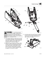
4. Remove the two capscrews (1) holding each wear
pad and shims to the transfer carriage (2).
5. Replace old wear pads with new wear pads (4) and
shims (3).
6. Coat the capscrews (1) with Loctite
®
242 (blue).
Secure in place with the two capscrews (1). Torque
capscrews to, 28 - 49 lb-ft (38 - 67 Nm).
11.3.6
Front Upstop Wear Pad Check
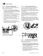
The front upstop wear pads (5) are located under the
frame rails at the front of the transfer carriage.
Each wear pad (5) is manufactured with a convenient
wear pad indicator. This is the angled cut (6) at each end
of all wear pads.
The total thickness (7) of a new wear pad (5) is 0.625"
(16 mm). The angled cut (6) will provide a total wear
thickness (8) of 0.25" (6 mm). This will leave
approximately 0.375" (10 mm) of total unused base
material.
The pads must never be worn past the angled cut
indicator because the metal pad insert (9), that holds the
pads in place, will begin to wear into the rail surfaces. If
the pad wears past this point, the metal insert in the pad
will begin to gouge the metal surfaces.
11.3.7
Front Upstop Wear Pad Gap Check
Note: The attachment should remain attached to the
quick attach for these checks.
1. Park the vehicle on level ground. Place the travel
select lever in the (N) NEUTRAL DETENT position,
engage the parking brake switch and raise the boom
to a horizontal (level) position.
2. Fully retract the boom and fully retract the transfer
carriage. Shut the vehicle OFF.
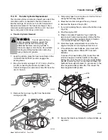
3. Check the gap (10) between the top of the wear
pad (5) and the bottom of the rail (11). The maximum
gap should be 0.12" (3 mm).
OU0960
1
2
3
4
OU1000
5
10
11
OU0990
6
7
8
9
Summary of Contents for 944E-42
Page 1: ......
Page 2: ......
Page 14: ...Safety Practices 1 8 Model 644E 42 944E 42 Rev 6 04 This Page Intentionally Left Blank...
Page 102: ...Boom 3 56 Model 644E 42 944E 42 Rev 6 04 This Page Intentionally Left Blank...
Page 139: ...4 37 Model 644E 42 944E 42 Rev 6 04 Cab and Covers This Page Intentionally Left Blank...
Page 144: ...Cab and Covers 4 42 Model 644E 42 944E 42 Rev 6 04 This Page Intentionally Left Blank...
Page 265: ...8 15 Model 644E 42 944E 42 Rev 6 04 Hydraulic System This Page Intentionally Left Blank...
Page 269: ...8 19 Model 644E 42 944E 42 Rev 6 04 Hydraulic System This Page Intentionally Left Blank...
Page 273: ...8 23 Model 644E 42 944E 42 Rev 6 04 Hydraulic System This Page Intentionally Left Blank...
Page 277: ...8 27 Model 644E 42 944E 42 Rev 6 04 Hydraulic System This Page Intentionally Left Blank...
Page 281: ...8 31 Model 644E 42 944E 42 Rev 6 04 Hydraulic System This Page Intentionally Left Blank...
Page 285: ...8 35 Model 644E 42 944E 42 Rev 6 04 Hydraulic System This Page Intentionally Left Blank...
Page 289: ...8 39 Model 644E 42 944E 42 Rev 6 04 Hydraulic System This Page Intentionally Left Blank...
Page 293: ...8 43 Model 644E 42 944E 42 Rev 6 04 Hydraulic System This Page Intentionally Left Blank...
Page 297: ...8 47 Model 644E 42 944E 42 Rev 6 04 Hydraulic System This Page Intentionally Left Blank...
Page 301: ...8 51 Model 644E 42 944E 42 Rev 6 04 Hydraulic System This Page Intentionally Left Blank...
Page 407: ...8 157 Model 644E 42 944E 42 Rev 6 04 Hydraulic System This Page Intentionally Left Blank...
Page 425: ...8 175 Model 644E 42 944E 42 Rev 6 04 Hydraulic System This Page Intentionally Left Blank...
Page 501: ...8 251 Model 644E 42 944E 42 Rev 6 04 Hydraulic System MT1950 2 3 4 5 6 7 8 5 5...
Page 507: ...8 257 Model 644E 42 944E 42 Rev 6 04 Hydraulic System MT1950 1 2 3 4 5 6 7 4 4...
Page 508: ...Hydraulic System 8 258 Model 644E 42 944E 42 Rev 6 04 This Page Intentionally Left Blank...
Page 525: ...9 17 Model 644E 42 944E 42 Rev 6 04 Electrical System This Page Intentionally Left Blank...
Page 554: ...Electrical System 9 46 Model 644E 42 944E 42 Rev 6 04 This Page Intentionally Left Blank...
Page 759: ...10 3 Model 644E 42 944E 42 Rev 6 04 Stabil TRAK System This Page Intentionally Left Blank...
Page 765: ...10 9 Model 644E 42 944E 42 Rev 6 04 Stabil TRAK System This Page Intentionally Left Blank...
Page 785: ...10 29 Model 644E 42 944E 42 Rev 6 04 Stabil TRAK System This Page Intentionally Left Blank...
Page 800: ...Stabil TRAK System 10 44 Model 644E 42 944E 42 Rev 6 04 This Page Intentionally Left Blank...
Page 832: ...Transfer Carriage 11 32 Model 644E 42 944E 42 Rev 6 04 This Page Intentionally Left Blank...
Page 840: ...12 8 Model 644E 42 944E 42 Rev 6 04 Index...
Page 841: ...Accident Prevention Tags OS2180 8990403 Origin 5 00 Accident Prevention Tags...
Page 842: ...Accident Prevention Tags OS2180 8990403 Origin 5 00...
Page 843: ......
Page 844: ......


