Lucent Technologies SuperPipe 95 Hardware Install Manual Download Page 8

8

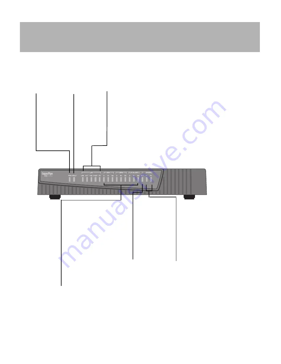
Refer to the following illustration to understand the functionality of the SuperPipe 155 and SuperPipe 95 
front panel LEDs.

Power
ON (green)= 
Power is being 
supplied to the 
unit.
OFF=Power is 
not being 
supplied to
the unit. 

Fault
OFF= 
Functioning 
correctly.
ON (red)=
Problem 
detected.

LAN LEDs
-----------------------------------------------------------------
LNK
ON (green)=Link active.
OFF= Link inactive.
ACT 
Flashes (green) when packets
are transmitted or received.
COL 
Flashes (amber) when
collisions are taking place 
on the Ethernet LAN.

10/100BT 
ON (green)= Link running 
at 100 Mbps.
OFF=Link running at 10 Mbps.
FD
ON (green)= Allows bidirectional, 
simultaneous communication (full 
duplex link). 
OFF=Information is carried in one 
direction at a time (half duplex link).

Phone Port Status
--------------------------
ON (amber)=Telephone port 
is in use.
OFF=Telephone port is available 
for use.
Flashing=Device connected to
telephone port is ringing.

T1/E1/V.35 Status
(SuperPipe 155)
-------------------------
ACT
ON= Active link.
FLASHING= Error.
OFF= Port 
disabled.

ISDN BRI LEDs
---------------------------------
B1/B2 Channel Activity 
GREEN = data call 
in progress.  
AMBER = voice call 
in progress.
Flashes when call is 
initiated.
D Channel Activity 
ON (green) =active ISDN line.  
OFF = ISDN line inactive.
Flashes when line activation 
is in progress. 


Understanding the SuperPipe LEDs

Summary of Contents for SuperPipe 95

Page 1: ...1 SUPERPIPE 95 155 HARDWARE INSTALL GUIDE Lucent Technologies Part Number 7820 0257 002 For software version 7 4 10 March 2000 ...

Page 2: ...or SuperPipe155 only one RJ 48C T1 crossover cable part number 2510 0059 001 Power plug adapters for international units Also please ensure that you have the following WAN interface s ISDN T1 or E1 service SuperPipe 155 only A computer with a serial port and a 10 100 Base T Ethernet interface If you have the V 35 version of the SuperPipe 155 you will need a V 35 X 21 cable ...

Page 3: ...ds RJ 48C to RJ 11 ISDN into one of the WAN BRI jacks on the back of the SuperPipe 2 Insert the other end of the cable into the ISDN wall jack 3 To connect an additional ISDN BRI line repeat steps 1 and 2 Connect an ISDN BRI line with an S interface To connect an ISDN BRI line with an S interface do the following Cable needed RJ 48C to RJ 11 ISDN cable provided has blue ends 1 Insert the larger ja...

Page 4: ...nterface equip ment 3 After you inform your service provider that your equipment is connected and ready for ser vice you are ready to start up the unit CAUTION The RJ 48C cable provided with your SuperPipe is for devices that transmit on pins 4 and 5 and receive on pins 1 and 2 Ask your carrier what type of cable to use a straight through or crossover V 35 Connection Cable needed DB44 to DB25 cabl...

Page 5: ...th the SuperPipe part number 2510 0084 001 to connect the SuperPipe to a 10 100 Base T hub Connect Superpipe to Computer s 3 3 Connect Analog Equipment The SuperPipe has two analog ports providing you with the option of using regular telephones or fax machines over your SuperPipe To connect a telephone or other analog telephone equipment 1 Connect one end of a modular telephone hookup cable to a c...

Page 6: ...r included with the SuperPipe to the plug 3 Connect the cable to the Terminal port on the back of the SuperPipe unit For Unix Users Cable needed Serial cable provided 1 Connect a modem cable for the computer to the Terminal port on the back of the SuperPipe 2 Connect the other end of the cable to the serial port on the computer For Macintosh Users Cable needed Serial cable you provide and a 25 pin...

Page 7: ...ord provided 3 Insert the opposite end of the power plug into an electrical outlet 4 Turn the power switch on the back panel to ON The PWR status light on the front pan els illuminates indicating that the power is on WARNING Models with AC power inputs are intended for use with a three wire grounding type plug that is a plug that has a grounding pin This is a safety feature Equipment grounding is ...

Page 8: ... at 100 Mbps OFF Link running at 10 Mbps FD ON green Allows bidirectional simultaneous communication full duplex link OFF Information is carried in one direction at a time half duplex link Phone Port Status ON amber Telephone port is in use OFF Telephone port is available for use Flashing Device connected to telephone port is ringing T1 E1 V 35 Status SuperPipe 155 ACT ON Active link FLASHING Erro...

Reviews: