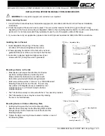
5/16" Hex Bolt
(monitor pivot tension adjustment)
CKLC100CRT71 Tubing Assembly
Socket Button Head Screw
(monitor tilt adjustment screw)
LC100 Pivot Assembly
LC100 Mounting Plate
Monitor Attaching Screws & Washers
Pr
o
te
c
te
d
u
n
d
e
r o
n
e
o
r m
o
re
o
f t
h
e
se
U
.S
. P
a
te
n
t n
um
b
e
rs:
3,
291,
432 3,
559,
942 3,
724
,798 D
ES
.270,
689 4,
613,
109
4,
878,
645 4
,852,
842 D
ES
.309,
5624,
973,
023 5,
169,
114
5,
255,
884 5,
310,
152 5,
522
,5
76 5,
621,
61
4 R
e
.35,
677 D
ES
.398,
834 5,
826,
384 5,
941
,492 5,
964,
06
8 6,
060,
661
6,
102,
398 6,
158,
704 6,
454,
11
6B
1 6,
761,
276B
2 6,
806,
425B
1
CKLC100CRT71
Page 2 of 2
CKLC100CRT71 INSTALLATION INSTRUCTIONS
6. Attach the monitor to the VESA Plate using hardware appropriate for the
threaded inserts on the monitor as specified by the manufacturer. Several
sizes of monitor attaching hardware have been provided for convienience.
7. Tighten the Tilt Plate Socket Button Head Screws to prevent the monitor
from tilting initially.
8. Align the hole on the Swivel Plate with hole on the Wall Arm.
CAUTION! For larger monitors, installation requires at least two people to
align the monitor and insert the 5/16" Hex Bolt. Attempting this installation
without assistance may result in accidental damage to the monitor.
9. Replace the 5/16" Hex Bolt, washers, nylock nut and cap used in Step 1.
10. Tighten the 5/16" Hex Bolt and Button Head Screws to provide the desired
tilting viewing angle and monitor position.
CAUTION! Do not leave the 5/16" Hex Bolt and Button Head Screws loose.
Leaving these screws loose may result in accidental damaged to the
monitor due to unrestricted movement.
CKLC100CRT71_Ins - 3/30/09 - M.R.B. ©2009 Lucasey Manufacturing Corporation, Oakland, California www.lucasey.com


