background image


- 9 - 

D370-019 


1 - START-UP 


1.1.


H

ANDLING AND 

S

TORAGE


The machine must be stored taking a minimum of precautions : 

- Machine on the ground, stable 
- Rear door closed and chute in the low position. 
- Ensure stems on all actuators are greased when kept in storage. Prior to operation, 

these same rods should be cleaned with a cloth moistened with diesel fuel and then 
dried with a clean, dry cloth. 

- Once uncoupled, the transmission must not be laid on the ground, but must rest on the 

mounting provided for the purpose. 

- The parking brake on. 


1.2.


T

RACTOR FITTINGS


Hydraulic fittings 
 

*  Hydraulic source 

. A single-acting hydraulic distributor (+ return) or a double-acting one (two female ½ clack valves). 
. Distributor maintained in continuous pumping. 
. Direct return to the tank recommended so as to reduce oil heating. 
. For self-regulating pumps, compulsory return to the bowl. 

*  Nominal flow rate : L8: 30 l - M8: 40 l - H8: 50 l (L - Low, M - Medium, H - High) 
*  Maximum pressure (bar) : 160. 
*  Circuit tape  :  

. The machines are factory set for open centre hydraulics. 

*  Closed centre hydraulics adaptation : Consult us 


 IMPORTANT 


The machine is capable of handling flows of up to 100 l/min. However, in order to save fuel, it is 
recommended that you adapt the flow to the belt advance rate being used (L, M, H). Above 55 
l/min, the additional flow will be unusable and will use up energy. 


 IMPORTANT 


In order for the controls to work in the right direction, make sure never to connect the hoses blue 
and red mark on the tractor the wrong way around. 

OIL POLLUTION IS NOT COVERED BY THE WARRANTY, KEEP THE VALVES CLEAN  


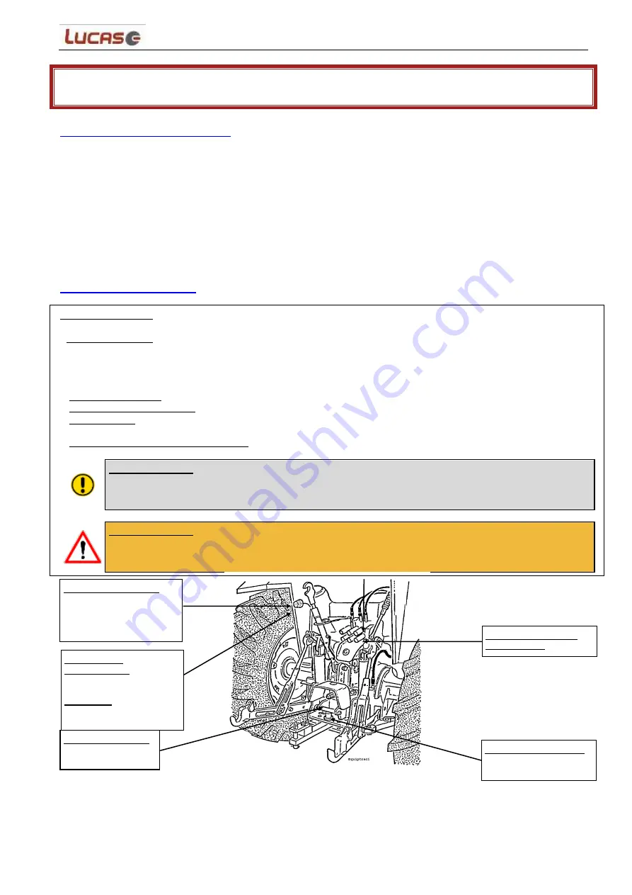
ELECTRIC FITTINGS  

Standard 12V 7 contact 

connector (European 

code) 

POWER TAKE-OFF 


6 straight 1"3/8 

splines 


EYE BOLT COUPLING 


with safety pin or fork 

joint coupling 

ELECTRICAL 

CONNECTION  

3 pin 12 volt DIN 9680 for 

power supply  

CAUTION 

: Current 

required 25 A 

HYDRAULIC BRAKE 

CONNECTOR  

Summary of Contents for Castor 134

Page 1: ...22 rue du stade 85130 LA VERRIE Tél 02 51 65 41 36 Réf D370 019 INSTRUCTION MANUAL INSTRUCTION MANUAL MASTER VERSION PLEASE READ CAREFULLY BEFORE USING THE MACHINE ...

Page 2: ...d maintenance procedures It has been drawn up for the CASTOR 134 and 185 line please refer to the paragraphs relating to your machine Some of the illustrations in this user s manual may have been made on the basis of prototype machinery The standard production models may differ with respect to certain details TO OBTAIN TOP PERFORMANCE FROM YOUR MACHINE PLEASE READ CAREFULLY ALL INSTRUCTIONS PROVID...

Page 3: ...r attempt to remove matter from the machine until it and the tractor have both come to a complete stop this recommendation is highly important for jobs using the distribution outlet where there is a risk of mutilating a finger or hand on the support plate or on the sections of the beater bar Whatever the type of intervention to be carried out greasing adjusting maintenance first stop the tractor e...

Page 4: ... a MAKER s plate located on the kit edge DO NOT REMOVE THE PLATES MOUNTED ON YOUR MACHINE WHAT TO DO IN THE EVENT OF A BREAKDOWN In the event of a failure or breakdown with your machine you should contact your dealer LUCAS G To avoid any confusion when ordering spare parts you will be asked to give the serial number of your machine NOTE Spare parts that have been disassembled will not be covered b...

Page 5: ...TORAGE 9 1 2 TRACTOR FITTINGS 9 1 3 COUPLING 10 1 4 CHECKING HYDRAULIC FUNCTIONS 11 1 5 CHECKING ROTATING PARTS 23 2 OPERATION 24 2 1 LOADING 24 2 2 LOADING USING THE HYDRAULIC DOOR OPTIONAL 25 2 3 TRANSPORT STORAGE 27 2 4 DISTRIBUTION 27 2 5 STRAW SPREADING 31 2 6 OPERATING FAILURES AND REMEDIES 33 2 7 WEIGHING 37 3 MAINTENANCE 38 3 1 MAINTENANCE POINTS 38 3 2 LUBRIFICATION PLAN 41 3 3 MAINTENANC...

Page 6: ...ance from the projection area while the machine is running Read the user manual It is absolutely forbidden to climb into the machine body Danger of chopping off fingers or the whole hand between the fan blades and the back plate or the sections of the beater bar Use some implement when clearing jammed material During operation no one must stand close to the machine Risk of crushing the fingers or ...

Page 7: ...raph in the user manual Periodically check the tightness of the wheels and the tyre pressures Keep warning notices and pictograms clean and visible at all times Ask your dealer for fresh stickers if they become damaged The part number is indicated on the bottom right side of the sticker When making repairs ensure that spare parts carry the same stickers as the original parts ...

Page 8: ...ht kg Gross vehicle weight rating kg 4 600 11 000 Toothed beater bar Side for distribution Straw spreading side Standard Option Drive Road lighting 2 fan rotation speeds at 540 rpm Pto Braking Standard tyre fitting Noise Db A Maximum authorised speed kph 3 Right Right 270 spreading area Power take off 540 rpm Yes 278 540 hydraulic 315 80 R22 5 77 25 ...

Page 9: ...ehicle weight rating kg 5 100 11 000 Toothed beater bar Side for distribution Straw spreading side Standard Option Drive Road lighting 2 fan rotation speeds at 540 rpm Pto Braking Standard tyre fitting Noise Db A Maximum authorised speed kph 3 Right Right 270 spreading area Power take off 540 rpm Yes 278 540 hydraulic 31 80 R 22 5 77 25 ...

Page 10: ...ps compulsory return to the bowl Nominal flow rate L8 30 l M8 40 l H8 50 l L Low M Medium H High Maximum pressure bar 160 Circuit tape The machines are factory set for open centre hydraulics Closed centre hydraulics adaptation Consult us IMPORTANT The machine is capable of handling flows of up to 100 l min However in order to save fuel it is recommended that you adapt the flow to the belt advance ...

Page 11: ...er s instructions The load on the front axle must not be less than 20 of the tractor s empty weight WARNING Take precautions to avoid getting trapped between the tractor and the machine When using the machine during travel no one will be found placed between the tractor and the machine WARNING Check that both the tractor and the machine brakes are really on 1 3 2 Checking the transmission shaft Fo...

Page 12: ...PRO control 1 4 1 1 Tractor equipment For optimum use of the control unit you must fit the control in the cabin using the stand provided 1 4 1 2 Components of the INTUITIVE PRO control system The control is located in the cabin mounted on the stand provided It is comprised of Green LED 1 Buzzer Shortcut buttons Supply 2 Diagnostic 3 Information 4 Menu 5 Screen control buttons 6 to 15 1 joystick Ke...

Page 13: ...ou must switch off the control In order to switch off the control and the machine you must hold down the Supply button button 1 for 2 seconds After 2 seconds the computer will take into account the shutdown request and will Emit a short beep Switch off the screen Switch off the LED The supply for the computer will be cut after 1 second 1 4 1 4 General cases 1 4 1 4 1 Return automatically to the co...

Page 14: ...agnostic Lets you access the machine s error codes Configure Lets you access the machine configuration Inspect Gives you different information such as the machine configuration the status of inputs outputs etc Adjust Lets you adjust certain machine parameters Maintenance Lets you approve maintenance once performed Secure Access the interface safeties Transfer Transfer images from the ECU to the in...

Page 15: ...se the chute pull and hold the joystick up Y To lower the chute pull and hold the joystick down Y To turn it left pull and hold the joystick left X To turn it right pull and hold the joystick right X Please note you can move on two axes at the same time e g raise up and rotate left etc When you release it the joystick will go back to neutral and control will stop If your machine is equipped with a...

Page 16: ...ive Active When the buttons are released the functions will return to inactive state Articulated comb hydraulic The articulated barrier blade is controlled using the buttons next to the screen To move the comb forward press and hold down on the button to the right of the icon Inactive Active To move the comb backwards press and hold down on the button to the left of the icon Inactive Active When t...

Page 17: ...nactive Active When the buttons are released the functions will remain active or inactive Distribution hatch The distribution hatch can be controlled using the buttons next to the screen To open the hatch press and hold down on the button to the right of the icon Inactive Active To close the hatch press and hold down on the button to the left of the icon Inactive Active When the buttons are releas...

Page 18: ...Button for 2 seconds will switch after decelerating to reverse and to max speed when the button is held down The information R will be displayed while in reverse When the button is released the speed will return to its previous speed minus 1 Stop Press then release button 14 to the right of the icon Particularities Speed curves M 3 Corresponds to curve M and speed 3 This system has 3 programmed sp...

Page 19: ... of the drive sprocket Replace the chain Tighten the chain see maintenance chapter Shredder frequency too low If the rotation frequency is too low the letter E will be displayed instead of the speed for a few seconds and the speed of the loading floor will return to 0 In this case Check if power grip has been activated if not switch it on safely Check the status and the functioning of the shredder...

Page 20: ...ain without you having to do anything Stop 1 To deactivate the atomiser when it is active press on the same button as for deactivation Inactive Active Second control box The second control post is a remote control post for the control While the second post function is active no functions which can be controlled from the secondary post can be used on the main control unit Similarly if the function ...

Page 21: ... will be used to update the loading floor speed value when the clutch is reactivated Following deactivation Should the loading floor be deactivated at any point during this deactivation activation phase the memorised speed will be reset to 0 Example The loading floor and the shredders are in operation You encounter an obstacle You deactivate the clutch With no information on the rotation of the sh...

Page 22: ... the maintenance page 1 4 1 4 5 Maintenance pages There are 2 maintenance pages the first for maintenance operations 1 to 10 and the second for maintenance operations 11 to 20 To switch between pages press the buttons next to the icons or Maintenance logo Confirmation logo Maintenance page 1 1 Machine maintenance hours N 1 2 Machine maintenance hours N 2 3 10 Machine maintenance hours N 10 Mainten...

Page 23: ...floor direction 0 Forward 1 Reverse 3 Speed curve used on the loading floor 4 Loading floor setpoint pwm in mA 5 Loading floor feedback pwm in mA 6 Machine operating time in hours 7 Machine operating time in seconds 8 Number of forced reversals WARNING Use of the by pass remains temporary in order to be able to continue using the machine in the event of the sensor breaking down or sustaining damag...

Page 24: ...the 540 rpm power take off on your tractor then gradually engage the clutch with the engine idling Then accelerate until the power take off is running at 540 rpm Inspect the rear of the machine to ensure that the fan and the toothed beater bar are being rotated correctly WARNING The machine can be fitted with an electromagnetic clutch that separates the beater bars fan rotation and enable them to ...

Page 25: ...3 It is recommended that you use even layers The advantage of this loading method is that it reduces the mixing time 2 1 1 Round bales Load round bales so that they roll in the body The winding direction is important see diagram below 2 1 2 Rectangular bales Load bales so that the knots are on the bottom Under no circumstances should the loaded product be jammed up against the shredders WARNING Th...

Page 26: ...door prior to putting it into the machine see diagram below Owing to a lack of visibility we would strongly advise that you DO NOT use the door with auto loading The maximum diameter of bales that can be loaded is 1 80 m Round bales of straw or hay with a diameter in excess of 1 50 m two in the box and one potentially on the rear door Round bales of straw or hay with a diameter smaller than 1 50 m...

Page 27: ...then pull using the loading floor or push using the loader to finish To load two 0 80 x 1 20 x 2 50 bales of straw you must lay the upper bale flat and back from the other so as to ensure an even flow the upper bale will break in two For 1 20 x 1 20 x 2 50 bales in principle with 2 bales in the box but it is possible to fit 2 bales in the box and 1 other half on the door and half on the loading fl...

Page 28: ...be used as a means of storage for round or parallelepipedal bales in order to increase the machine s mulching capacities bales pending see diagram below WARNING During transportation the offset of the rear of the machine in relation to the wheels is highly important when the door is in a horizontal position Pay attention during turns or in tight passing places WARNING Driving on roads with the doo...

Page 29: ...g Select your forward tractor speed according to the volume to be fed Always stop the base conveyor first Then wait until there are no more projections from the front chute before disengaging the power take off Using a magnetic extractor optional remove any metal particles after each distribution Table of recommended power take off rotation speeds for the DISTRIBUTION function BASE COMPOSITION POW...

Page 30: ...ltering the position of the screws provided for this purpose 1 Remove the two selection screws nuts A on each side of the chute 2 Loosen the two retention screws B on each side without removing them 3 Adjust the angle of the cap to suit your requirements by selecting one of the five possible positions using screws A 4 Screw in the two screws nuts A 5 Retighten the two screws nuts B ...

Page 31: ...ting silage on the top of the runner It is recommended to unlock the arm when distributing hay or when using wrapped round bales on the bottom of the runner Open the feed chute and place it for well directed projection Select the low fan speed position Engage the tractor power take off then gradually accelerate Start the base conveyor moving forward Gradually increase the conveyor speed until you ...

Page 32: ...er by adding the chute extension kit ref 43512 950 A Upon loading see 2 1 Put the articulated comb in maximum advanced position Open the distribution chute and position it until it is in the desired mulching position The link rod is in the locked position Select the fast speed position of the fan Engage the tractor power take off then gradually accelerate The engine speed should be adjusted to sui...

Page 33: ...en gradually accelerate The engine speed should be adjusted to suit the straw spreading conditions and distance to be reached Start the base conveyor moving forward Gradually increase the conveyor speed until you reach the optimum feed rate Take care not to make this feed rate too high as this may cause jamming Select your forward tractor speed according to the volume of straw to be spread and the...

Page 34: ...afety reasons To do this you must Be on the manual control page Press and then release button 14 to the right of the icon to initiate the loading floor Not active Active Press and hold down on Button 15 for 2 seconds While the button is being held down the loading floor after deceleration will move into reverse and switch to max speed When you release the button the speed will return to its previo...

Page 35: ...en combs and discs 3 1 Turn the beater bar of a revolution and with a wedge adjust a play of 5 mm between the upper part of the disc and the end of the comb Tighten the combs respecting a torque of 45Nm Adjust the combs so that they are opposite the discs Recommendations POSITION FLOW Corn short grass Full ration Flow Hay Round bales of hay 1 Maximum OK for all short products Full payload Ok grass...

Page 36: ...tter If this occurs frequently check the play on the support plate 3 3 2 Power take off speed too low Adjust the speed as per instructions Drive chain comes off Chain slack Tighten the chain Base conveyor chain comes off Chain slack Tighten the chain Base conveyor chain comes off frequently Base conveyor worn Chain wheels worn See your LUCAS dealer Irregular straw flow Straw protection flap not wo...

Page 37: ...e shredder drive break down IMPORTANT Emergency procedure you must repair your machine as quickly as possible To use the machine without using the rotation sensor you must Press then release the Menu button to access the menu Press then release the Safeties button to access the menu for safety Press then release the button next to the by pass icon The icon should then change becoming identical to ...

Page 38: ... T During initial coupling or when changing tractor use all of the adjustments in order to make sure the box is in the best possible position 2 7 3 Machine configuration In order for the weighing system to work The machine must be coupled to the tractor the machine must not rest on the stand The weighing light must be lit To ensure an accurate weight it is recommended that the machine be positione...

Page 39: ...aning Prior to each stoppage for the putting away of the machine it is necessary to carry out thorough cleaning and degreasing Cleaning with a gush of water is enough to remove the products gathered during the working period These products contribute to the acceleration of the oxidisation process of your machine It is thus necessary to clean in accordance with the frequency given in the table A hi...

Page 40: ...yor drive shaft bearing Grease cardan joints transmission Grease mixing net bearing Check base conveyor chain tension Lubricating the chute collar Box oil level Drain housing Wheel hub Tighten all nuts Gush of water 1 x mois Replacing the hydraulic filter Checking the tightness of the sections Changing sections beater bars 3 1 3 Checking the tyres TYRE DESCRIPTION NOMINAL INFLATION PRESSURE WHEEL ...

Page 41: ... level and empty the two speed gear box The oil level is fine if the oil flows when you unscrew the cap in the middle of the box To top up the oil Disassemble the transmission and the protective casing Loosen the screws located at the top of the box in the middle Fill via the opening at the top until the oil flows through the hole in the middle of the box To change the gearbox oil Loosen the drain...

Page 42: ... to make sure that the hand brake is working properly control lever and the tension of the ropes Check the status of the hydraulic braking system tube and jack Disassemble the brake drum flanges in order to check the jaws for wear 3 2 LUBRIFICATION PLAN ...

Page 43: ...oor 2 Unscrew rear fastening screw 3 Fasten inspection door back into place for your own safety Risk of injury 4 Hook machine up to the tractor 5 Set unit to fast 6 Set machine turning at an operating pressure of 540 tr min 7 Adjusting the appropriate screws to bring the support plate slowly up to the fan 8 If you hear the sound of the support plate coming into contact with the fan move the suppor...

Page 44: ...2 Tighten the 3 screws HC M10 Ref 3 to get a play of 1 mm Tighten again the 4 screws FHC M12 Ref 2 Unblock the fan Mount again the chute upper and lower parts Remark If the play is still important please contact your LUCAS G dealer to replace the contra rotating blade WARNING You are in a dangerous area Ensure that your tractor and machine are stable and your handbrake is on You are working in pro...

Page 45: ...the chain should separate from the bottom of the body of 10 cm 3 Re tension the apron if necessary using the two tension screws located at the rear of the body The tension should be equal on both sides and the idler shaft must remain parallel to the rear cross member When the tensioner system is at the end of the maximum stroke and the chain is slack take out two links on each of the chains WARNIN...

Page 46: ...n braking by pressing the brake pedal from the driving position Effective braking means a stopping distance of 10 metres at 25 km hr on the road and parking of the machine carrying its maximum permitted load on an 18 slope If these performances are not obtained the braking system requires maintenance clean drums take up play change linings tension control cables hydraulic pressure in the valve the...

Page 47: ...e the machine on a hard floor on a slight slope to the door side so as to avoid any water remaining inside the tank Place all connections on their respective mountings If you perform all these operations your machine will be ready to restart with no further attention 3 5 DISMANTLING AND DISPOSAL Drain the gearboxes and oil circuits When dismantling separate into different categories of material ir...

Page 48: ...ukt Auquel se réfère cette déclaration est conforme aux dispositions de la Directive Machines 2006 42 CEE Le soussigné est désigné pour présenter le dossier technique s y référant To which this declaration refers in compliance with the provisions of the Machines Directive 2006 42 EEC The undersigned is appointed for producing the relative technical papers Auf wem sich diese Erklarüng bezieht die C...

Reviews: