


2
1.2.3 Model: 9:1 Pneumatic oil pump
1.2.3.1 Specification: 108bar
(
Max. fluid working pressure
)
1.2.3.2 Configuration:
Sheet 3: 9:1 Pneumatic oil pump
Remark: with 3/4"M to 1/2"F reducer.
1.2.3.3 Max. free flow rate: 20L/min.
1.3 Safety instructions
1.3.1
WARNING:
No complying with below requests will result in severely harm to your body even death.
1.3.2 Oil pump misuse hazard: Oil pump misuse can cause the to rupture, malfunction
• Read all instruction manuals, tags, and labels before operating the equipment.
• Use the equipment only for its intended purpose. If you are not sure, call your distributor.
• Do not alter or modify this equipment. Use only genuine parts and accessories.
• Check equipment daily. Repair or replace worn or damaged parts immediately.
• Do not exceed the maximum working pressure of the lowest rated component in your system.
• Use fluids and solvents which are compatible with the equipment wetted parts. Refer to the
Technical Data section of all equipment manuals. Read the fluid and solvent manufacturer's warnings.
• Do not use 1,1,1-trichloroethane, methylene chloride, other halogenated hydrocarbon solvents, or
fluids containing such solvents in pressurized aluminum equipment. Such use could result in a
chemical reaction, with the possibility of explosion.
• Handle hoses carefully. Do not pull on hoses to move equipment.
• Route hoses away from traffic areas, sharp edges, moving parts, and hot surfaces.
• Do not lift pressurized equipment.
• Wear adiabatic glove when operate pump.
• Do not move or lift pump during use.
• Comply with all applicable local, state, and national fire, electrical, and safety regulations.
1.3.3 SKIN INJECTION HAZARD
Fluid from the dispensing valve, leaks, or ruptured components can inject fluid into your body and
cause extremely serious injury, including the need for amputation. Fluid splashed in the eyes or on
the skin can also cause serious injury. If a fluid injection injury occurs,
GET IMMEDIATE
SURGICALTREATMENT. Do not treat as a simple cut.
• Do not point the dispensing valve at anyone or at any part of the body.
• Do not put your hand or fingers over the end of the dispensing valve.
• Do not stop or deflect leaks with your hand, body, glove or rag.
• Use only extensions and no-drip tips which are designed for use with your dispensing valve.
• Do not use a low pressure flexible nozzle with this equipment.
• Follow the Pressure Relief Procedure if the dispensing valve clogs before you clean, check or
service the equipment.
• Tighten all fluid connections before operating the equipment.
• Check the hoses, tubes, and couplings daily. Replace worn or damaged parts immediately.
• Do not repair high pressure couplings; you must replace the entire hose.
3
1.3.4 MOVING PARTS HAZARD
Moving parts can pinch or amputate your fingers.
• Do not operate the pump with the air motor plates removed.
• Keep clear of all moving parts when starting or operating the pump.
• Before servicing the equipment, follow the Pressure Relief Procedure to prevent the equipment
from starting unexpectedly.
1.3.5 FIRE AND EXPLOSION HAZARD
Improper grounding, poor ventilation, open flames or sparks can cause a hazardous condition and
result in a fire or explosion and serious injury.
• Ground the equipment and the object being lubricated.
• If there is any static sparking or you feel an electric shock while using this equipment, stop
dispensing immediately. Do not use the equipment until you identify and correct the problem.
• Provide fresh air ventilation to avoid the buildup of flammable fumes from solvents or the fluid
dispensed
• Keep the dispensing area free of debris, including solvent, rags, and gasoline.
• Do not smoke in the dispensing area.
2 Technical Data
Pneumatic Oil Pumps Technical Data:
3 Grounding and Installation
3.1 Grounding
3.1.1 Warning: Before use the pump, check grounding of the
whole system to prevent fire and explosion
3.1.2 To reduce the risk of static sparking, each device should
ground effectively.
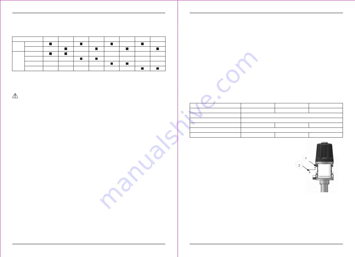
Pump: Use a ground wire and clamp as the Fig.2. Get rid of
the grounding screw, put the end of the grounding wire into
the grounding hole. Lock the bolt to the pump safety.
Air and Fluid hoses: Grounding effectively.
Air compressor: Follow manufacturer's recommendations.
Oil control valve: Connect the pump with proper grounding wire,
always hold a metal part of the valve firmly to the side of a
grounded metal pail, then trigger the valve.
Barrel: Use local applicable trolley. If it is metal barrel, put on the device which is electric, can not put
on insulative device surface, such as paper or carton board which without grounding.
Other parts: Operated with local regulation for grounding.
Fluid supply container: Follow the local code.
Model
1/4"quick plug
1/4"NPT
270mm
730mm
940mm
1190mm
Air inlet
Length
of
suction
tube
17130901 17130903 17130931 17130933 17130961 17130963 17130971 17130973
Model Series
Pressure Ratio
Air Inlet Working Pressure
Max. Air Inlet Pressure
Max. Oil Outlet Pressure
Air Motor Effective Diameter
Max. Free Flow Rate
171305 Series
171303 Series
3:1
5-10 bar
12 bar
36 bar
108mm
60bar
5:1
45L/min
40L/min
171309 Series
108bar
9:1
20L/min
FIG.2: Grounding guide


