background image

Network Video Recorder Quick Start Guide 

26 

Chapter 4 


Accessing by Web Browser 


You shall acknowledge that the use of the product with Internet access might be under network security risks. 
For avoidance of any  network attacks and information  leakage,  please strengthen your own  protection. If the 
product does not work properly, please contact with your dealer or the nearest service center. 
Purpose: 
You can get access to the device via web browser. You may use one of the following listed web browsers: 
Internet Explorer 6.0, Internet Explorer 7.0, Internet Explorer 8.0, Internet Explorer 9.0, Internet Explorer 10.0, 
Apple Safari, Mozilla Firefox, and Google Chrome. The supported resolutions include 1024*768 and above.   
Steps: 
1.


Open web browser, input the IP address of the device and then press Enter. 

2.


  Login to the device.   

l


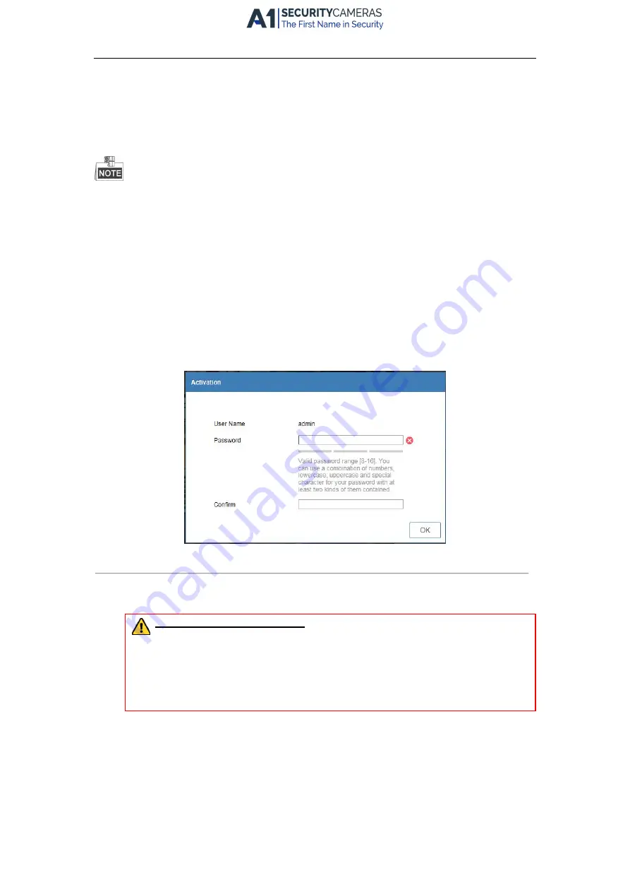
If the device has not been activated, you need to activate the device first before login.     


Figure 4. 2


Set Admin Password 


1)


Set the password for the admin user account. 

2)


Click OK to login to the device.   

STRONG PASSWORD RECOMMENDED

– We highly recommend you create a strong password of 

your own choosing (using a minimum of 8 characters, including upper case letters, lower case 
letters, numbers, and special characters) in order to increase the security of your product. And 
we  recommend  you  reset  your  password  regularly,  especially  in  the  high  security  system, 
resetting the password monthly or weekly can better protect your product. 


l


If the device is already activated, enter the user name and password in the login interface, and click 

the Login button. 

                 Available from A1 Security Cameras 

    www.a1securitycameras.com email: [email protected]

Summary of Contents for 87 K-P Series

Page 1: ...Network Video Recorder Quick Start Guide Available from A1 Security Cameras www a1securitycameras com email sales a1securitycameras com...

Page 2: ...2 3 2 Alarm Output Wiring 15 2 3 3 Using Alarm Connectors 15 2 3 4 Controller Connection 16 2 4 HDD Storage Calculation Chart 17 Chapter 3Menu Operation 18 3 1 Menu Structure 18 3 2 Startup and Shutdo...

Page 3: ...EMPLOYEES OR AGENTS BE LIABLE TO YOU FOR ANY SPECIAL CONSEQUENTIAL INCIDENTAL OR INDIRECT DAMAGES INCLUDING AMONG OTHERS DAMAGES FOR LOSS OF BUSINESS PROFITS BUSINESS INTERRUPTION OR LOSS OF DATA OR...

Page 4: ...Conformity Statement This product and if applicable the supplied accessories too are marked with CE and comply therefore with the applicable harmonized European standards listed under the EMC Directi...

Page 5: ...to the power socket If smoke odor or noise rise from the device turn off the power at once and unplug the power cable and then please contact the service center Preventive and Cautionary Tips Before c...

Page 6: ...l is applicable to the following models Series Model Type 87XXK P series 8CH 8POE 16CH 16POE Network Video Recorder 88XXK series 16CH 32CH 88XXK P series 16CH 16POE 32CH 16POE Available from A1 Securi...

Page 7: ...tion Indicates a potentially hazardous situation which if not avoided could result in equipment damage data loss performance degradation or unexpected results Provides additional information to emphas...

Page 8: ...ion is met Tx Rx Blinks green when network connection is functioning normally 4 SHIFT Switch between the numeric or letter input and functions of the composite keys Input letter or numbers when the li...

Page 9: ...put Double press the button to switch the main and auxiliary output 6 Compound Buttons DIRECTION In menu mode the direction buttons are used to navigate between different fields and items and select s...

Page 10: ...ields and items and select setting parameters In playback mode the Up and Down buttons are used to speed up and slow down record playing and the Left and Right buttons are used to move the recording 3...

Page 11: ...d clipping in playback 6 MNO PLAY Enter numeral 6 Enter letters MNO Playback for direct access to playback interface 7 PQRS REC Enter numeral 7 Enter letters PQRS Open the manual record interface 8 TU...

Page 12: ...ut Display local video output and menu 4 HDMIInterface HDMI video output connector 5 ALARM IN Connector for alarm input ALARM OUT Connector for alarm output 6 LAN Network Interface 1 10 100 1000 Mbps...

Page 13: ...B mouse and USB Hard Disk Drive HDD 6 RS 232 Interface Connector for RS 232 devices 7 VGA DB9 connector for VGA output Display local video output and menu 8 RS 485 Interface Half duplex connector for...

Page 14: ...Environmental temperature should be within the range of 10 to 55 C 14 to 131 F 8 Environmental humidity should be within the range of 10 to 90 2 2 Hard Disk Installation Before you start Disconnect th...

Page 15: ...ct the power cable to the HDD Figure 2 4 Connect Power Cable 4 Place the HDD on the bottom of the device and then fasten the screws on the bottom to fix the HDD Figure 2 5 Fix Hard Disk Available from...

Page 16: ...ad the jumpers can be used within the limit of 12V 1A safely To connect an AC load jumpers should be left open you must remove the jumper on the motherboard in the NVR Use an external relay for safety...

Page 17: ...nnection To connect a controller to the NVR 1 Disconnect pluggable block from the KB terminal block 2 Unfasten stop screws from the KB D D pluggable block insert signal cables into slots and fasten st...

Page 18: ...84M 224K 98M 256K 112M 320K 140M 384K 168M 448K 196M 512K 225M 640K 281M 768K 337M 896K 393M 1024K 450M 1280K 562M 1536K 675M 1792K 787M 2048K 900M 4096K 1 8G 8192K 3 6G 16384K 7 2G Please note that s...

Page 19: ...lectrical outlet It is HIGHLY recommended that an Uninterruptible Power Supply UPS be used in conjunction with the device The Power button on the front panel should be red indicating the device is rec...

Page 20: ...in the text field of Create New Password and Confirm New Password Figure 3 4 Set Admin Password STRONG PASSWORD RECOMMENDED We highly recommend you create a strong password of your own choosing Using...

Page 21: ...ssword 3 4 Login and Logout 3 4 1 User Login Purpose If NVR has logged out you must login the device before operating the menu and other functions Steps 1 Select the User Name in the dropdown list Fig...

Page 22: ...hutdown menu Menu Shutdown Figure 3 8 Logout 2 Click Logout After you have logged out the system menu operation on the screen is invalid It is required to input a user name and password to unlock the...

Page 23: ...e the system resolution system date time network settings HDD management record settings etc Figure 3 9 Wizard 3 6 Network Settings Purpose Network settings must be properly configured before you oper...

Page 24: ...r record the video files you should add the network cameras to the connection list of the device Before you start Ensure the network connection is valid and correct and the IP camera to add has alread...

Page 25: ...detailed information Purpose Two kinds of record types are introduced in the following section including Instant Record and All day Record And for other record types you may refer to the user manual...

Page 26: ...channel list and then double click to select a date on the calendar 3 You can use the toolbar in the bottom part of Playback interface to control playing progress Figure 3 13 Playback Interface Select...

Page 27: ...browser input the IP address of the device and then press Enter 2 Login to the device l If the device has not been activated you need to activate the device first before login Figure 4 2 Set Admin Pa...

Page 28: ...installation prompts to install the plug in You may have to close the web browser to finish the installation of the plug in After login you can perform the operation and configuration of the device in...

Reviews: