background image

Card Reader      User Manual 

11 

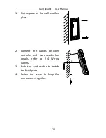
1.


Fix the plate on the wall or other 
place. 

1


2.


Connect  the  cables  between 
controller  and    card  reader.  For 
details,  refer  to  2.4  Wiring 
Cables. 

2

3

4


3.


Push  the  card  reader  to  match 
the fixed plate. 

4.


Fasten  the  screw  to  keep  the 
components together. 


Summary of Contents for LTK1101 Series

Page 1: ...LTK1101 LTK1104 Series Card Reader User Manual ...

Page 2: ...DING TO THE PRODUCT WITH INTERNET ACCESS THE USE OF PRODUCT SHALL BE WHOLLY AT YOUR OWN RISKS OUR COMPANY SHALL NOT TAKE ANY RESPONSIBILITES FOR ABNORMAL OPERATION PRIVACY LEAKAGE OR OTHER DAMAGES RESULTING FROM CYBER ATTACK HACKER ATTACK VIRUS INSPECTION OR OTHER INTERNET SECURITY RISKS HOWEVER OUR COMPANY WILL PROVIDE TIMELY TECHNICAL SUPPORT IF REQUIRED SURVEILLANCE LAWS VARY BY JURISDICTION PL...

Page 3: ...the instruction manual may cause harmful interference to radio communications Operation of this equipment in a residential area is likely to cause harmful interference in which case the user will be required to correct the interference at his own expense FCC Conditions This device complies with part 15 of the FCC Rules Operation is subject to the following two conditions 1 This device may not caus...

Page 4: ... for specific battery information The battery is marked with this symbol which may include lettering to indicate cadmium Cd lead Pb or mercury Hg For proper recycling return the battery to your supplier or to a designated collection point For more information see www recyclethis info Industry Canada ICES 003 Compliance This device meets the CAN ICES 3 A NMB 3 A standards requirements Safety Instru...

Page 5: ...en disconnected before you wire install or dismantle the device When the product is installed on wall or ceiling the device shall be firmly fixed If smoke odors or noise rise from the device turn off the power at once and unplug the power cable and then please contact the service center If the product does not work properly please contact your dealer or the nearest service center Never attempt to ...

Page 6: ...r extra bright places A blooming or smear may occur otherwise which is not a malfunction however and affecting the endurance of sensor at the same time Please use the provided glove when open up the device cover avoid direct contact with the device cover because the acidic sweat of the fingers may erode the surface coating of the device cover Please use a soft and dry cloth when clean inside and o...

Page 7: ...ernal 12V range 10 10 DC power supply which is nonswitched and linear To guarantee the communication between the controller and the card reader you must use RVVP cable above 0 5 to connect them If the card reader is installed outside or in environment easy to permeable it is advisable to install a waterproof shield If you need to install several card readers the distance among them must over 30cm ...

Page 8: ...on 2 1 1 Front View 2 1 2 Rear View 3 1 3 Side View 4 Chapter 2 Installation 6 2 1 Installing PSAM Card 6 2 2 Introduction for DIP Switch 6 2 3 Definition of Cable 7 2 4 Wiring Cables 8 2 5 Installing Card Reader 10 Chapter 3 Sound Prompt and Indicator 12 ...

Page 9: ... either RS 485 protocol or Wiegand protocol And a build in tamper proof module helps to protect card reader from malicious damage As to the physical appearance the PC ABS material makes water proof and dust proof possible in poor environment 1 1 Front View The card reader of LTK1101 is shown below Figure 1 1 LTK1101MK Figure 1 2 LTK1101M The card reader of LTK1104 is shown below ...

Page 10: ...Card Reader User Manual 3 Figure 1 3 LTK1104MK Figure 1 4 LTK1104M 1 2 Rear View The rear view of card reader is shown below 1 2 3 4 5 Figure 1 5 Rear View of LTK1101 ...

Page 11: ...w of LTK1104 Table 1 1 Description of Rear View No Name 1 Cable Interface of RS 485 Power LED Control etc 2 Buzzer 3 Tamper proof Module 4 DIP Switch 5 PSAM Card Slot available for CPU card reader 1 3 Side View The side view of card reader is shown below ...

Page 12: ...Card Reader User Manual 5 Figure 1 7 LTK1101 Figure 1 8 LTK1104 ...

Page 13: ...ng to the direction shown below Figure 2 1 PSAM Card Slot 2 2 Introduction for DIP Switch The DIP switch module is shown below The No of DIP switch from left to right is 1 8 Figure 2 2 DIP Switch Module Table 2 1 Description of DIP Switch Icon Description Represent 1 in binary mode Represent 0 in binary mode For example binary value of the following status is 0000 1100 ...

Page 14: ...n card 6 Wiegand protocol or RS 485 protocol 1 Wiegand protocol 0 RS 485 protocol 7 Wiegand Protocol available when No 6 is 1 1 Wiegand protocol of 26 bit 0 Wiegand protocol of 34 bit 8 Matched Resistance available for RS 485 protocol 1 Enable 0 Disable 2 3 Definition of Cable The description of 10 cables is shown below Table 2 3 Description of Cable Color Description Yellow RS 485 Brown Blue LED ...

Page 15: ... Red LED Control available for Wiegand Protocol Red PWR DC 12V 2 4 Wiring Cables Purpose Wire the cables between controller and card reader thus to establish the communication between them Steps for RS 485 communication mode 1 Set the DIP switch of No 6 as 0 2 Set the DIP switch of No 1 5 for RS 485 address and reading card mode For details please refer to 2 2 Introduction for DIP Switch 3 Wire th...

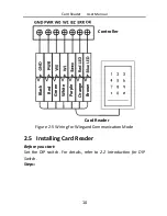
Page 16: ... RS 485 Communication Mode Steps for Wiegand communication mode 1 Set the DIP switch of No 6 as 1 2 Set the DIP switch of No 5 and 7 for reading card mode and Wiegand protocol For details please refer to 2 2 Introduction for DIP Switch 3 Wiring the cable between controller and card reader as shown below ...

Page 17: ...ck Red Green White Purple Orange Brown Controller Card Reader Figure 2 5 Wiring for Wiegand Communication Mode 2 5 Installing Card Reader Before you start Set the DIP switch For details refer to 2 2 Introduction for DIP Switch Steps ...

Page 18: ...e plate on the wall or other place 1 2 Connect the cables between controller and card reader For details refer to 2 4 Wiring Cables 2 3 4 3 Push the card reader to match the fixed plate 4 Fasten the screw to keep the components together ...

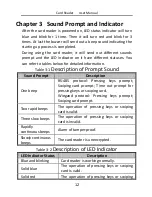
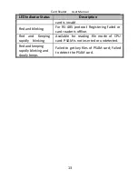
Page 19: ...rompt Sound Sound Prompt Description One beep RS 485 protocol Pressing keys prompt Swiping card prompt Time out prompt for pressing keys or swiping card Wiegand protocol Pressing keys prompt Swiping card prompt Two rapid beeps The operation of pressing keys or swiping card is valid Three slow beeps The operation of pressing keys or swiping card is invalid Rapidly continuous beeps Alarm of tamper p...

Page 20: ...For RS 485 protocol Registering failed or card reader is offline Red and Keeping rapidly blinking Available for reading file mode of CPU card PSAM is not inserted or undetected Red and keeping rapidly blinking and slowly beeps Failed to get key files of PSAM card Failed to detect the PSAM card ...

Reviews: