


Digital Video Recorder User Manual
31
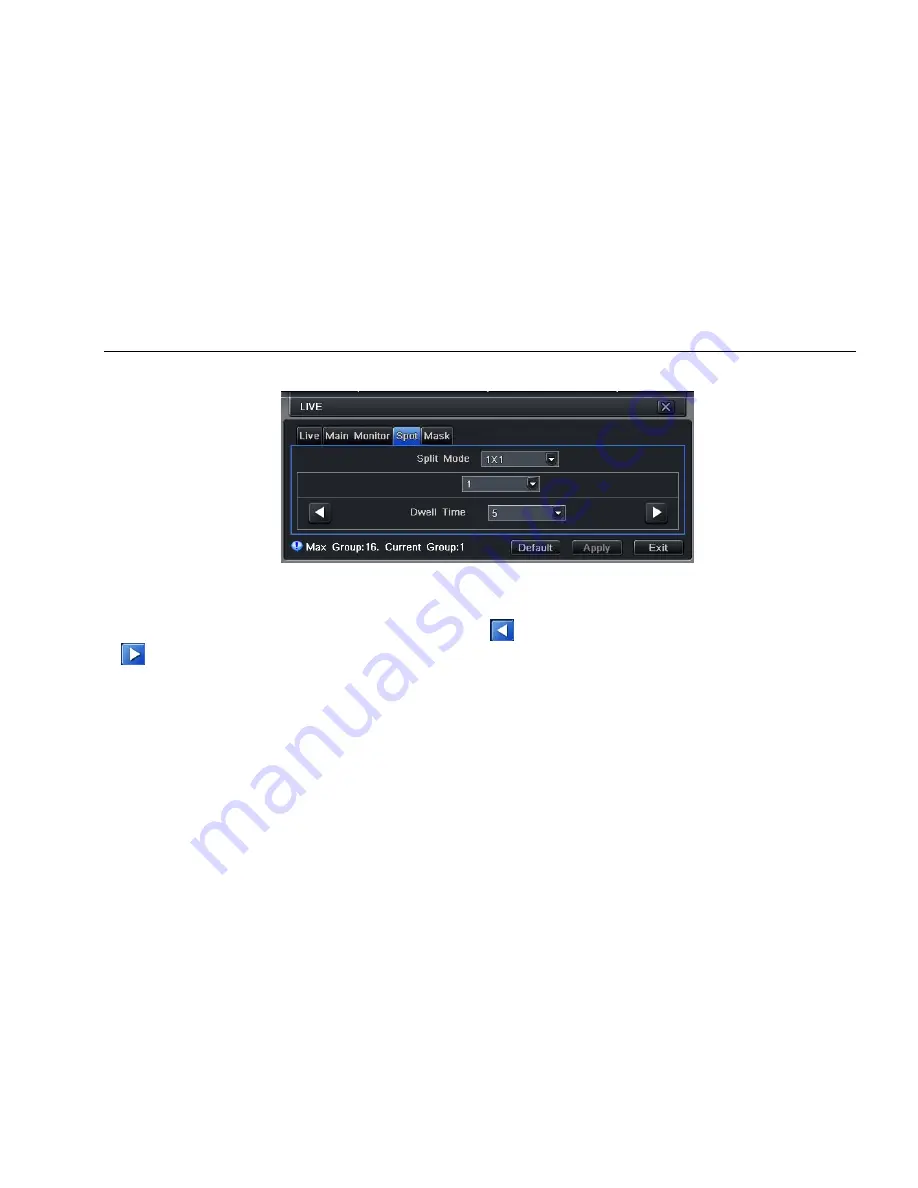
4.2.3 SPOT
Step1: enter into system configuration
Æ
live configuration
Æ
SPOT; refer to Fig 4-9:
Fig 4-9 live configuration-SPOT
Step2: select split mode: 1
×
1and channel
Step3: dwell time: the time interval for a certain dwell picture display switching to next dwell picture display
Step4: selected the split mode, then setup current picture group. Click
button to setup the previous channel groups of dwell picture, click
button to set the latter channel groups of dwell picture.
Step5: click “default” button to resort default setting; click “apply” button to save the setting; click “exit” button to exit current interface
4.2.4 Mask
User can setup private mask area on the live image picture, max threes areas.


