


iS7 Encoder Setup
2
LSIS iS7 Encoder Setup
Rev A_10-31-2018
Wiring
Wire the motors encoder wires to the encoder card using the below reference table.
Terminal
Function
S
Shield connection
A+
Positive A channel pulse (A)
A-
Negative A channel pulse (/A)
B+
Positive B channel pulse (B)
B-
Negative B channel pulse (/B)
G
Ground connection, common for DC supplies below.
5V
5VDC supply to encoder
12V
12VDC supply to encoder
15V
15VDC supply to encoder
RTA/RTB
Return Pulse for channel A and B (open collector
output)
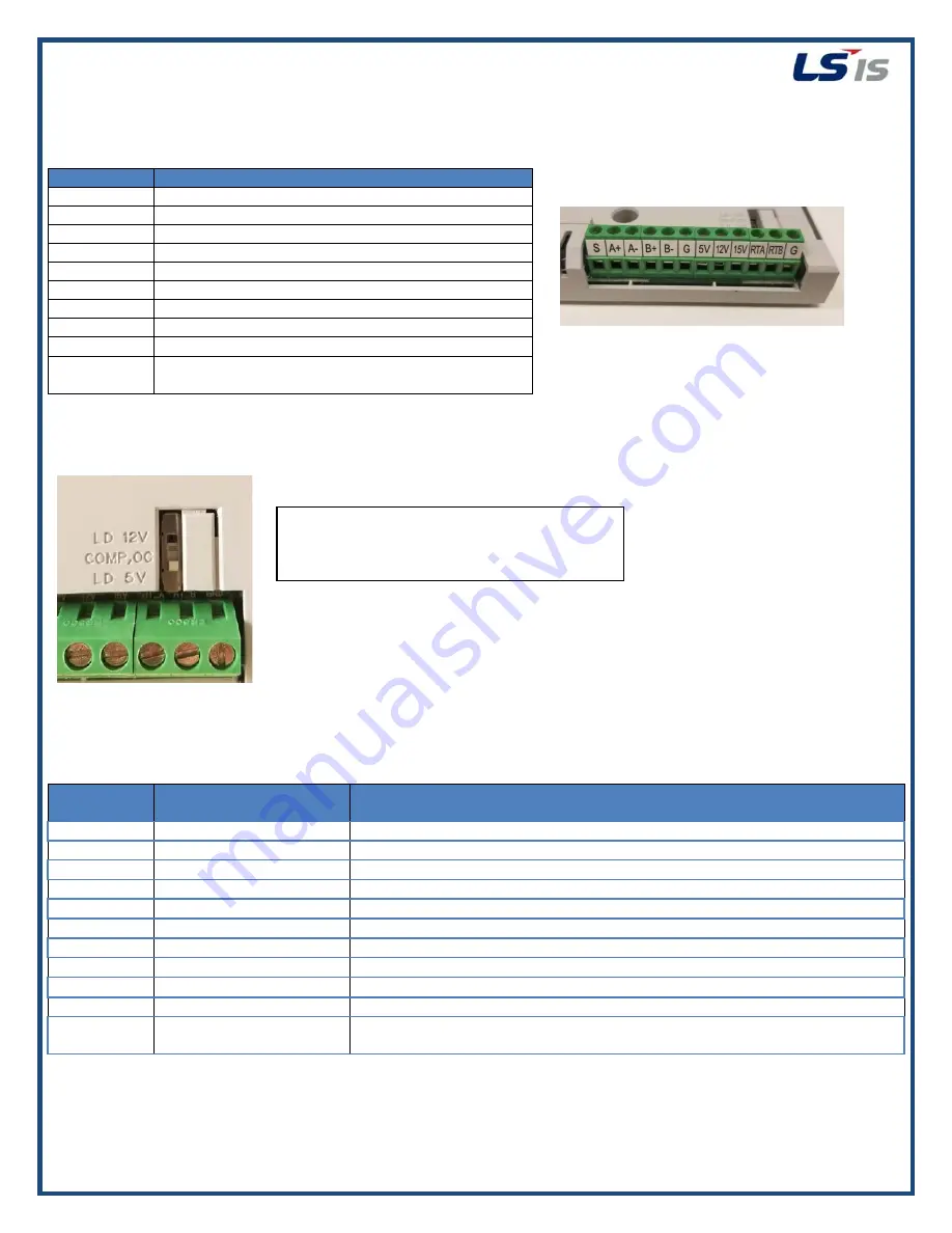
The encoder card supports line driver type and open collector type encoders. Be sure to set the switch pictured below to
the correct setting depending on the applied encoder.
Parameter Setup
It is imperative to setup the below parameters and conduct and autotune to ensure proper operation of the iS7 with
encoder feedback.
Parameter
Code
Parameter Name
Recommended Setting
APO-01
Encoder Option Mode
1 – Feedback
APO-04
Encoder Type Selection
Set to line driver or open collector based on installed encoder
APO-05
Encoder Pulse Selection
Leave at A+B if using both channels
APO-06
Encoder Pulse #
Set to PPR of encoder
DRV-09
Control Mode
5 - Vector
DRV-14
Motor Capacity
Set to motor kW
BAS-11
Motor Poles
Set to # of motor poles
BAS-12
Rated Slip
Set to rated motor slip
BAS-13
Rated Current
Set to motor FLA
BAS-15
Rated Voltage
Set to rated motor voltage
BAS-20
Auto Tuning
1-All
**This will rotate the motor, ensure motor is uncoupled from the
load**
LD 12V = Line Driver 12VDC
COMP, OC = Complementary/ Open collector
LD 5V = Line Driver 5VDC


