


Learning Basic Features
130
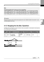
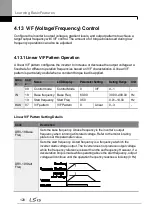
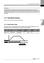
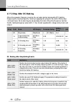
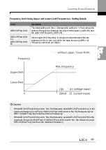
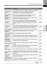
4.17.2 Stop After DC Braking
When the operation frequency reaches the set value during deceleration (DC braking
frequency) the inverter stops the motor by supplying DC power to the motor. With a stop
command input, the inverter begins decelerating the motor. When the frequency reaches
the DC braking frequency set at ADV-17, the inverter supplies DC voltage to the motor and
stops it.
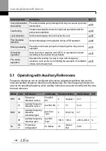
Group Code
Name
LCD Display
Parameter Setting
Setting
Range
Unit
ADV
08
Stop mode
Stop Mode
1
DC Brake
0
–4
-
14
Output block time
before braking
DC-Block
Time
0.00
0.00
–60.00
sec
15
DC braking time
DC-Brake
Time
1.00
0
–60
sec
16
DC braking amount
DC-Brake
Level
50
0
–200
%
17
DC braking
frequency
DC-Brake
Freq
5.00
0.00
–60.00
Hz
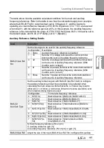
DC Braking After Stop Setting Details
Code
Description
ADV-14 DC-
Block Time
Set the time to block the inverter output before DC braking. If the inertia of
the load is great, or if DC braking frequency (ADV-17) is set too high, a fault
trip may occur due to overcurrent conditions when the inverter supplies DC
voltage to the motor. Prevent overcurrent fault trips by adjusting the output
block time before DC braking.
ADV-15 DC-
Brake Time
Set the time duration for the DC voltage supply to the motor.
ADV-16 DC-
Brake Level
Set the amount of DC braking to apply. The parameter setting is based on
the rated current of the motor.
ADV-17 DC-
Brake Freq
Set the frequency to start DC braking. When the frequency is reached, the
inverter starts deceleration. If the dwell frequency is set lower than the DC
braking frequency, dwell operation will not work and DC braking will start
instead.
Summary of Contents for H100
Page 14: ......
Page 18: ...Preparing the Installation 4 37 90 kW 3 Phase ...
Page 27: ...Preparing the Installation 13 ...
Page 47: ...33 Installing the Inverter ...
Page 48: ...Installing the Inverter 34 Input and Output Control Terminal Block Wiring Diagram ...
Page 61: ...47 Installing the Inverter ...
Page 71: ...Learning to Perform Basic Operations 57 ...
Page 88: ...Learning to Perform Basic Operations 74 ...
Page 103: ...89 Learning Basic Features Code Description V1 Quantizing ...
Page 129: ...115 Learning Basic Features ...
Page 140: ...Learning Basic Features 126 ...
Page 148: ...Learning Basic Features 134 ...
Page 171: ...157 Learning Advanced Features Deceleration dwell operation ...
Page 183: ...169 Learning Advanced Features ...
Page 184: ...Learning Advanced Features 170 PID Command Block ...
Page 185: ...171 Learning Advanced Features PID Feedback Block ...
Page 186: ...Learning Advanced Features 172 PID Output Block ...
Page 187: ...173 Learning Advanced Features PID Output Mode Block ...
Page 197: ...183 Learning Advanced Features ...
Page 201: ...187 Learning Advanced Features Code Description 100 EPID1 Control block ...
Page 202: ...Learning Advanced Features 188 EPID2 Control block ...
Page 237: ...223 Learning Advanced Features Time Period Schedule AP3 38 Except3 Day 01 01 ...
Page 244: ...Learning Advanced Features 230 ...
Page 259: ...245 Learning Advanced Features Code Description Code Description Volt ...
Page 362: ...Learning Protection Features 348 ...
Page 415: ...401 RS 485 Communication Features Item Standards Parity check None ...
Page 524: ...Table of Functions 510 ...
Page 533: ...Table of Functions 519 ...
Page 547: ...533 Troubleshooting ...
Page 585: ...Technical Specification 571 ...
Page 594: ...580 ...
Page 595: ...581 ...
Page 596: ...582 ...


