2 of 3
describes the jumpers and the connectors
on the controller.
Step 4
Install the MegaRAID SATA 150-6 RAID
Controller
on the Mainboard
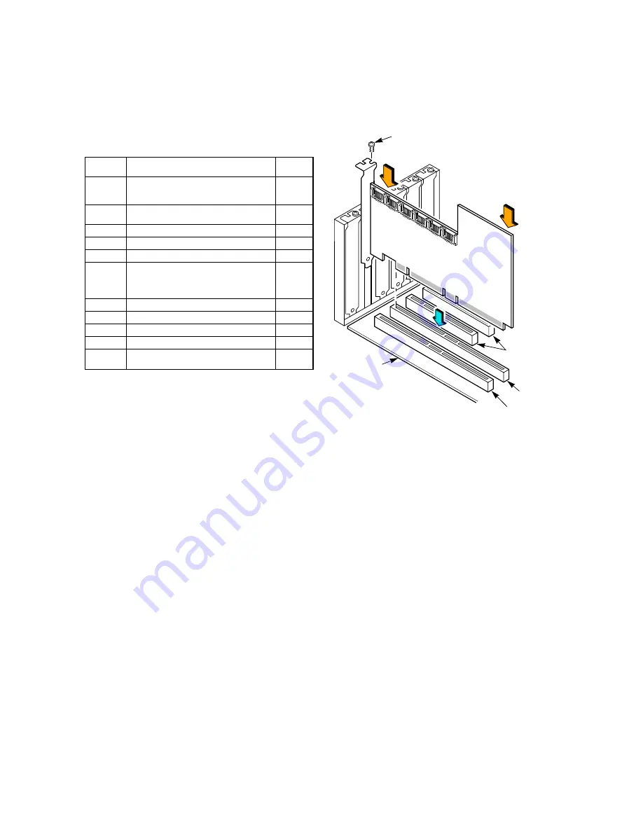
Insert the MegaRAID SATA 150-6 RAID
Controller in a PCI slot on the mainboard, as
shown in
. Press down gently but firmly
to seat the card properly in the slot. Secure the
MegaRAID SATA 150-6 RAID Controller to the
computer chassis with the bracket screw.
Figure 2 Installing the MegaRAID SATA 150-6
RAID Controller
Step 5
Configure and Install the SATA Devices in the
Host Computer Case
Refer to the documentation for the SATA devices
for any pre-installation configuration
requirements.
Step 6
Connect the SATA Cables
Connect the SATA cables between the system’s
onboard SATA150-6 RAID Controller and the
SATA devices. Refer to the system’s
documentation to view connector locations for the
server.
The MegaRAID SATA 150-6 provides six Serial
ATA connectors. J7, J8, J9, J10, J11, and J12 are
the Serial ATA Port 0, 1, 2, 3, 4, and 5
connectors, respectively.
provides the
location of the connectors on the MegaRAID
SATA 150-6.
Table 1
Jumpers and Connectors
Jumper,
Connector Description
Setting
J1
Reserved for internal use.
Do not install a jumper on J1.
Open
J2
Open – BIOS enabled
Installed – BIOS disabled
Open
J3
UART serial I/O connector for test
Open
J4
Connector for Write Pending Indication LED Optional
J5
Serial I/O connector for Serial EPROM
Open
J6
I
2
C connector used as the interface for the
controller to communicate with a storage
enclosure processor (SEP) in an enclosure
arrangement
Open
J7-J12
Port connectors. See
for details.
Optional
J13
Enables Mode 0 Select
Open
J14
Enables 3.3 V load sharing from mainboard Optional
J15
Battery backup daughter card connector
Optional
J16, J17,
JP1
Reserved for internal use
–
Bracket Screw
Edge of
Mainboard
32-bit
5 V, 64-bit
3.3 V, 64-bit
PCI Slot
PCI Slot
Press Here
Press Here
PCI Slots


