


3-6
Technical Specifications
3.2.3 The LED Interface
The LED interface on the LSI8751D is a four-wire arrangement that
allows the user to connect an LED harness to the board. The
GPIO0_FETCH line (maximum output low voltage 0.4 V and minimum
output low current 16 mA) is pulled low to complete the circuit when a
harness with an LED is attached. The connector on the LSI8751D is J4.
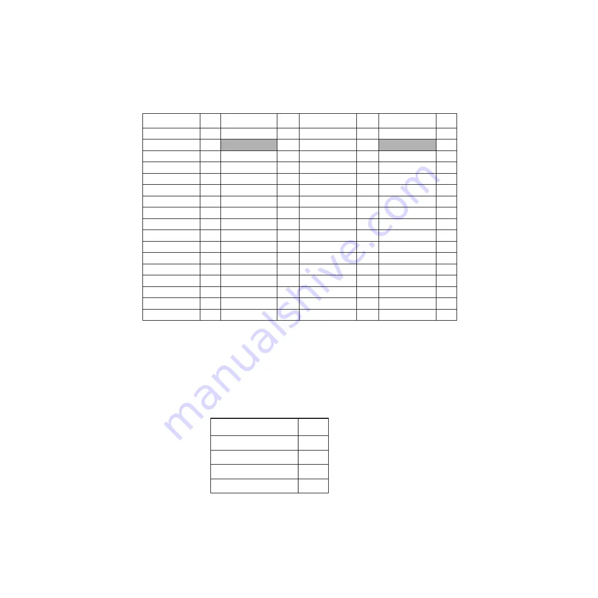
Table 3.4
SCSI Connectors J2 and J3
Signal Name
Pin
Signal Name
Pin
Signal Name
Pin
Signal Name
Pin
+DB(12)
1
TERMPWR
18
−
DB(12)
35
TERMPWR
52
+DB(13)
2
RESERVED
19
−
DB(13)
36
RESERVED
53
+DB(14)
3
+ATN
20
−
DB(14)
37
-ATN
54
+DB(15)
4
GND
21
−
DB(15)
38
GND
55
+DB(P1)
5
+BSY
22
−
DB(P1)
39
−
BSY
56
GND
6
+ACK
23
GND
40
−
ACK
57
+DB(0)
7
+RST
24
−
DB(0)
41
−
RST
58
+DB(1)
8
+MSG
25
−
DB(1)
42
−
MSG
59
+DB(2)
9
+SEL
26
−
DB(2)
43
−
SEL
60
+DB(3)
10
+C/D
27
−
DB(3)
44
−
C/D
61
+DB(4)
11
+REQ
28
−
DB(4)
45
−
REQ
62
+DB(5)
12
+I/O
29
−
DB(5)
46
−
I/O
63
+DB(6)
13
GND
30
−
DB(6)
47
GND
64
+DB(7)
14
+DB(8)
31
−
DB(7)
48
−
DB(8)
65
+DB(P)
15
+DB(9)
32
−
DB(P)
49
−
DB(9)
66
DIFFSENS
16
+DB(10)
33
GND
50
−
DB(10)
67
TERMPWR
17
+DB(11)
34
TERMPWR
51
−
DB(11)
68
Table 3.5
LED Connector J4
Signal Name
Pin
LED+
1
LED
−
2
LED
−
3
LED+
4
Summary of Contents for LSI8751D
Page 1: ...LSI8751D PCI to SCSI Host Adapter USER S GUIDE Au g u s t 2 0 0 1 Version 3 0...
Page 4: ...iv...
Page 8: ...ii Contents Appendix A Glossary of Terms and Abbreviations Customer Feedback...
Page 10: ...iv...
Page 12: ...vi...
Page 16: ...1 4 Describing the LSI8751D...
Page 38: ...2 22 Installing the LSI8751D...
Page 52: ...A 8 Glossary of Terms and Abbreviations...
Page 54: ...IX 2...