2-10
Installing the LSI20160
Copyright © 2001 by LSI Logic Corporation. All rights reserved.
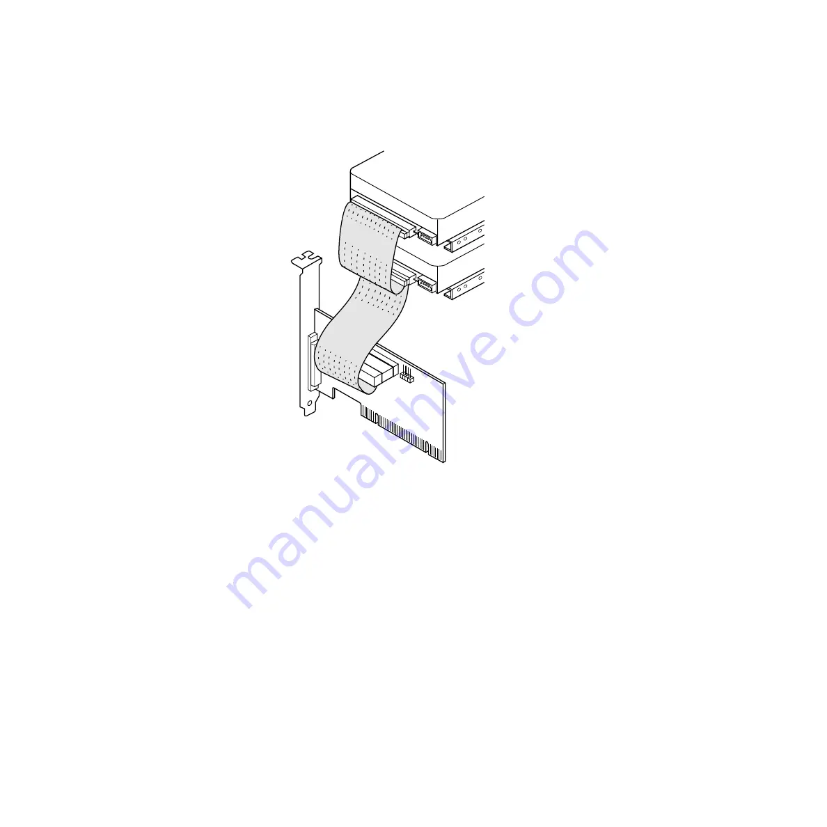
Figure 2.7
Multiple Internal SCSI Devices Chained Together
2.2.4.2 Making Activity LED Connection
Most PC cabinets are designed with a front panel LED to indicate bus
activity. It may already be connected to an existing IDE controller. If you
want, you can connect the LED to the SCSI LED connector.
Connect the LED cable to J3 on your SCSI host adapter, as shown in
.
The Busy LED connector J3 is not keyed. The J3 connector is a 4-pin
one row right angle header. Some LED cables have only two wires. In
this case, place the connector on one end of J3. If the LED does not light
during SCSI bus activity, you may have to rotate the LED cable 180˚ on
J3 or move it to the other end of the jack.
Summary of Contents for LSI20160
Page 4: ...iv Copyright 2001 by LSI Logic Corporation All rights reserved...
Page 10: ...x Copyright 2001 by LSI Logic Corporation All rights reserved...
Page 12: ...xii Copyright 2001 by LSI Logic Corporation All rights reserved...
Page 48: ...3 10 Technical Specifications Copyright 2001 by LSI Logic Corporation All rights reserved...
Page 62: ......


