LSI ITI7004G2-, User Manual
The LSI ITI7004G2- is a cutting-edge product designed to meet your technological needs. Ensure optimal performance by downloading the free User Manual from our website. Get step-by-step guidance on how to maximize the features of this product. The Manual is your key to unlocking its full potential.
Share
Download


Reviews:
No comments
Related manuals for ITI7004G2-

BDRS01
Brand: Baracoda Pages: 10
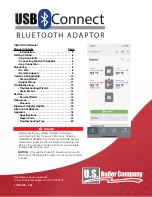
USB-Connect
Brand: U.S. Boiler Company Pages: 20

WALL MAX
Brand: I-GO Pages: 2

1346300
Brand: Renkforce Pages: 8

NI 6584R
Brand: National Instruments Pages: 20

VMCHVM
Brand: KILLARK Pages: 2

PRESTO GIGABIT SERVER PCIe
Brand: Sonnet Pages: 4

WL-161
Brand: Asus Pages: 21

USB-AC56R
Brand: Asus Pages: 2

USB-BT500
Brand: Asus Pages: 48

XG-C100C
Brand: Asus Pages: 2

USB-C2500
Brand: Asus Pages: 4

WL-167G V3
Brand: Asus Pages: 13

USB-BT211 Mini Bluetooth Dongle
Brand: Asus Pages: 41

USB-AC55
Brand: Asus Pages: 4

WL-BTD 202
Brand: Asus Pages: 54

WL-330NUL
Brand: Asus Pages: 128
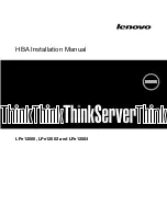
ThinkServer LPe12000
Brand: Lenovo Pages: 22


