


199
Learning Advanced Features
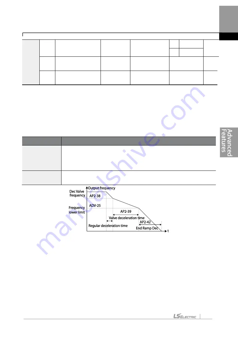
This function is used to prevent pump damage due to abrupt deceleration. When the pump
operation frequency reaches the valve ramp frequency (
AP2-38 Dec Valve Freq) while
decelerating rapidly based on the deceleration ramp time (set at AP2-42), it begins to slow
down the deceleration based on the deceleration valve ramp time (set at
AP2-39
DecValve
Time).
Decelerating valve ramp operates when ADV-
24 (Freq Limit) is set to ‘1 (Yes)’.
Deceleration Valve Ramping Setting Details
The time set at AP2-39 refers to the absolute time that it takes for the pump to decelerate
from the frequency set at AP2-38 to the frequency limit set at ADV-25.
5.17 Load Tuning
Load tuning refers to an operation that detects the load applied to a specific section of the
inverter operation (current and voltage) and creates an ideal load curve for the under load
and pump clean operations. The two set points to define the section are user-definable, and
are set at 50% and 85% of the base frequency (DRV-18 Base Freq) by default. The load
tuning result values are saved at codes AP2-2
–AP2-10. These values are user definable as
ADV
24
Frequency limit
options
Limit Mode
0: No
0
No
-
1
Yes
25
Low Freq minimum
value
Freq Limit
Lo
30.00
Start Freq
–
Max Freq
Hz
26
Low Freq maximum
value
Freq Limit
Hi
60.00
Freq Limit Lo
–
Max Freq
Hz
Code
Description
AP2-38 Dec
Valve Freq
Sets the start frequency where the slow deceleration begins in order to
prevent pump damage when the inverter stops. Decelerating valve
ramping is performed from the frequency set at AP2-38 to the frequency
limit set at ADV-25 (low frequency limit for pump operation).
AP2-39
DecValve Time
Sets the time it takes to decelerate from the frequency set at AP2-38 to the
frequency limit set at ADV-25 (low frequency limit for pump operation).
Summary of Contents for LSLV-H100 Series
Page 17: ...Preparing the Installation 4 37 90 kW 3 Phase ...
Page 18: ...Preparing the Installation 5 110 132 kW 3 Phase ...
Page 19: ...Preparing the Installation 6 160 185 kW 3 Phase ...
Page 20: ...Preparing the Installation 7 220 250 kW 3 Phase ...
Page 21: ...Preparing the Installation 8 315 400 kW 3 Phase ...
Page 22: ...Preparing the Installation 9 500 kW 3 Phase ...
Page 35: ...Installing the Inverter 22 ...
Page 50: ...37 Installing the Inverter Input and Output Control Terminal Block Wiring Diagram ...
Page 104: ...91 Learning Basic Features 0 10 V Input Voltage Setting Details V1 Quantizing ...
Page 181: ...168 Learning Advanced Features PID Command Block ...
Page 182: ...169 Learning Advanced Features ...
Page 183: ...170 Learning Advanced Features PID Feedback Block ...
Page 184: ...171 Learning Advanced Features PID Output Block ...
Page 185: ...172 Learning Advanced Features PID Output Mode Block ...
Page 198: ...185 Learning Advanced Features EPID1 Control block ...
Page 199: ...186 Learning Advanced Features EPID2 Control block ...
Page 220: ...207 Learning Advanced Features ...
Page 235: ...222 Learning Advanced Features The Time Chart for the Exception Day ...
Page 506: ...Table of Functions 493 ...
Page 520: ...Table of Functions 507 8 16 4 Cooling Tower MC4 Group ...
Page 549: ...Troubleshooting 536 ...
Page 569: ...Technical Specification 556 11 3 External Dimensions 0 75 30 kW 3 phase 37 90 kW 3 phase ...
Page 570: ...Technical Specification 557 110 185 kW 3 phase ...
Page 601: ...588 ...
Page 602: ...589 ...
Page 603: ...590 ...


