


MultiController E 0-100%
LS Control A/S
Side 7
2.7
Scheduler Menu (B-Menu)
The integrated scheduler function is a week scheduler with possibility of 10 shifts
per day. The scheduler function is enabled / disabled in the user menu (C3).
If scheduler is activated, an icon appears in the main window.
B1:
Scheduler is programmed in menu B:
Main menu
A systeminfo
B Scheduler/time
C User
D Display
E Service
F Modbus
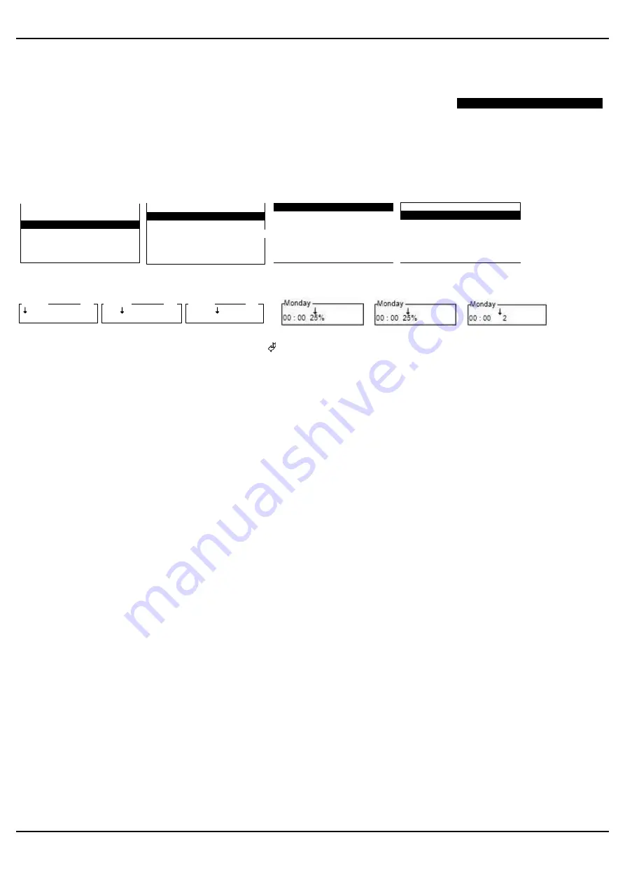
B Scheduler
B1 Scheduler shift
B2 Scheduler reset
B3 Copy scheduler
B4 Date and time
B5 Save/open scheduler
01 Monday
02 Tuesday
03 Wednesday
04 Thursday
05 Friday
06 Saturday
07 Sunday
Monday
01 00 : 00 - - - -
02 00 : 00 - - - -
03 00 : 00 - - - -
04 00 : 00 - - - -
05 00 : 00 - - - -
06 00 : 00 - - - -
Monday
00 : 00 - - - -
01
Monday
00 : 00 - - - -
01
Monday
00 : 00 - - - -
01
E.g.
or
or
Set time for the requested shift and press “enter”
Then set required level (OFF/ON, 0-100%, Step 1-4)
Repeat above steps for required numbers of days and shifts per day.
NB! A shift is only active if required level is different from ----
Note it is possible to change the setpoint manually in the main window (unless locked by security level). However at
next scheduler shift the controller will return to the preset setpoint value from scheduler.
B2:
Scheduler Reset.
This menu point resets the scheduler.
Note:
All settings in scheduler is deleted!
B3:
Scheduler Copy.
Copy all scheduler setting from one weekday to another. Previous settings are overwritten by this copying function.
B4:
Date and Time.
The date, weekday and time for the MultiController is set in this menu.
Clock is a 24-hour clock. Optional choice of automatic shift between summer and normal time.
MultiController E has integrated battery back-up for the clock ensuring that short power cuts do not affect the clock.
In case of longer power cuts (> 72 hours) the clock must be reset.
B5:
Save / Retrieve Scheduler.
It is possible to copy all scheduler settings by using the “Save/Open Scheduler” function. Insert a MicroSD-card
(according to specifications) in the Multicontroller and press save. Then move the SD-card to the next
MultiController and retrieve the settings via menu B5 and press ’Open’.
2.8
User Menu (C-Menu)
The user menu consists of the most frequently used configuration controls.
C1:
Level / setpoint is adjusted in this menu point. (Has no function in 4-step / 2-step PIR setting)
Level / setpoint may be altered from main window (arrow up/down). However, this is only active until next
scheduled event.
B Scheduler
B1 Scheduler shift
B2 Scheduler reset
B3 Copy scheduler
B4 Date and time
B5 Save/open scheduler


