- Instruction Manual for ESS R050096 -
38
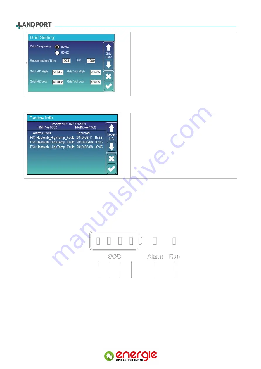
VDE0126, AS4777, IEC62109:
No need to set the function of this interface.
General Standard:
Please select the correct Grid Frequency in your
local area.
You can hold this in default value.
4.2.10 Device info setup menu
This page show Inverter ID, Inverter version and
alarm codes.
HMI: LCD version MAIN: MCU version
4.3 Battery status display
The SOC and running status of the battery pack can be checked through the LED status indicator
on the battery pack. The indicators are sorted from left to right as LED1-LED6. The LED5 and LED6
of the 1# battery pack show the fault summary status of the battery cabinet, That is, when any
battery pack of the system fails, the LED of the 1# battery pack displays the current failure.
Picture
4-2 Intent of battery display window
LED1 LED2 LED3 LED4
LED5
LED6


