background image

L-Proxy User Manual 

58 

LOYTEC  

Version 3.1 


LOYTEC electronics GmbH   


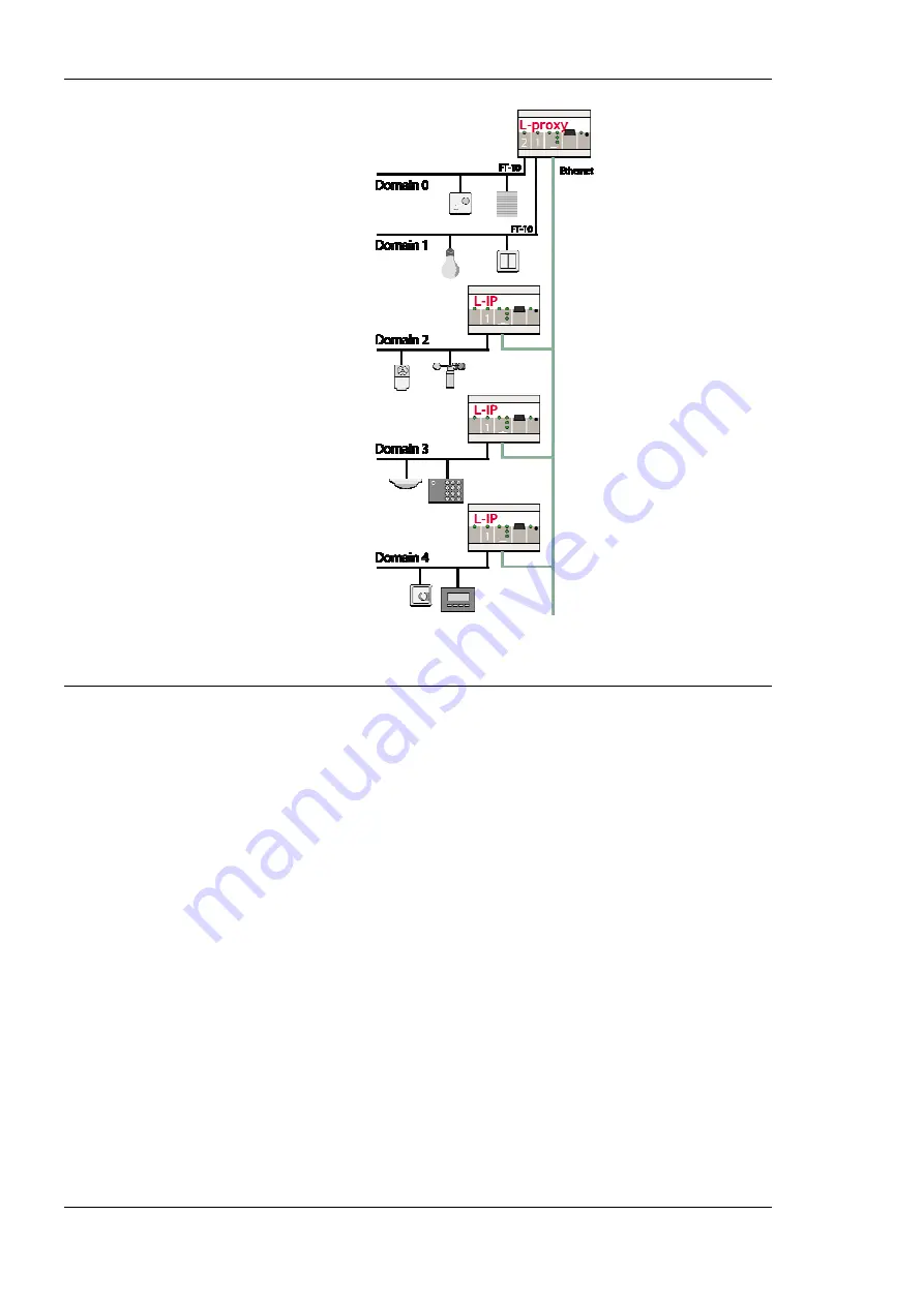
Figure 56: Connecting the IP-852 ports to other channels using L-IPs. 

6.3 Data Points 

6.3.1 Overview 

Data points are part of the fundamental device concept to model process data. A data point 
is the basic input/output element on the device. Each data point has a value, a data type, a 
direction, and a set of meta-data describing the value in a semantic context. Each data point 
also has a name and a description. The entire set of data points is organized in a hierarchy. 

At the data point level, the specific technological restrictions are abstracted and hidden 
from the user. Working with different technologies at this level involves common work-
flows for all supported technologies. 

The direction of a data point is defined as the “network view” of the data flow. This means, 
an input data point obtains data from the network. An output data point sends data to the 
network. This is an important convention to remember as different technologies may define 
other direction semantics. 

The basic classes of data points are: 


Analog

: An 

analog

 data point typically represents a scalar value. The associated data 

type is a 

double precision

 machine variable. Meta-data for analog data points include 

information such as value range, engineering units, precision, and resolution. 


Binary

: A 

binary

 data point contains a Boolean value. Meta-data for binary data 

points includes human-readable labels for the Boolean states (i.e., active and inactive 
texts). 

Summary of Contents for L-Proxy

Page 1: ...L Proxy CEA 709 Gateway User Manual LOYTEC electronics GmbH ...

Page 2: ...SUSTAIN LIFE FOR USE IN FLIGHT CONTROL OR ENGINE CONTROL EQUIPMENT WITHIN AN AIRCRAFT OR FOR ANY OTHER APPLICATION IN WHICH IN THE FAILURE OF SUCH PRODUCT COULD CREATE A SITUATION IN WHICH PERSONAL INJURY OR DEATH MAY OCCUR No part of this publication may be reproduced stored in a retrieval system or transmitted in any form or by any means electronic mechanical photocopying recording or otherwise ...

Page 3: ...hernet Link LED 19 3 4 5 Ethernet Activity LED 19 3 4 6 CNIP LED 19 3 4 7 Config LED 20 3 4 8 Wink Action 20 3 5 Status Button 20 3 6 DIP Switch Settings 20 3 7 Terminal Layout and Power Supply 20 3 8 Wiring 21 4 Console Interface 22 4 1 Console Connection 22 4 2 Self Test 22 4 3 L Proxy Device Main Menu 23 4 3 1 Option 1 Show device information 23 4 3 2 Option 2 Serial firmware upgrade 24 4 3 3 O...

Page 4: ...ion 0 NTP Servers 28 4 6 6 Option b Link Speed Duplex 28 4 7 CEA 852 Device Configuration Menu 29 4 7 1 Option 2 Config server address 3 Config server port 29 4 7 2 Option 4 Config client port 29 4 7 3 Option 5 Device name 29 4 7 4 Channel Mode 30 4 7 5 SNTP server channel timeout 30 4 7 6 Option 6 Escrow timeout 30 4 7 7 Option 7 Aggregation Timeout 30 4 7 8 Option 8 MD5 authentication 30 4 7 9 O...

Page 5: ... 2 6 Data Points 45 5 3 Device Statistics 47 5 3 1 IP Statistics 47 5 3 2 CEA 852 Statistics 48 5 3 3 Enhanced Communications Test 49 5 3 4 CEA 709 Statistics 50 5 3 5 System Log 50 5 4 Reset Contact Logout 51 6 Concepts 52 6 1 What is a Proxy 52 6 1 1 Update Update Use Case 53 6 1 2 Poll Poll Use Case 53 6 1 3 Update Poll Use Case 53 6 1 4 Poll Update Use Case Active Poll 53 6 1 5 Use Case Combin...

Page 6: ...ows for the L Proxy 73 7 4 1 Involved Configuration Files 73 7 4 2 Configure with LNS and Dynamic NVs 73 7 4 3 Configure with LNS and Static NVs 75 7 4 4 Configure without LNS using Static NVs 77 7 4 5 Change an Existing Configuration with LNS 78 7 4 6 Change an Existing Configuration without LNS 79 7 4 7 Replace an L Proxy 80 7 5 Adding L Proxy 81 7 6 Creating Functional Blocks Virtual Interfaces...

Page 7: ...ystem Log 117 7 11 Connections 118 7 11 1 Create a New Connection 118 7 11 2 Auto Create Connections for NVs 119 7 11 3 Generate and Connect from NVs 119 7 11 4 Create Connections from a CSV File 121 7 11 5 Modify Connections 121 7 11 6 Connection Overview 122 8 Application Scenarios 123 8 1 Address Table Extension 123 8 1 1 Saving Entries in the Address Table 123 8 1 2 Saving a Group Address 125 ...

Page 8: ...stallation 143 12 4 Move L Proxy into a new LNS project 143 12 5 Node does not respond to poll request 144 12 6 L Proxy doesn t forward packets after commissioning 144 12 7 Technical Support 145 13 Application Notes 146 13 1 The LSD Tool 146 13 2 Use of Static Dynamic and External NVs on a Device 146 14 Firmware Versions 147 15 Specifications 148 15 1 L Proxy 148 15 1 1 Physical Specifications 148...

Page 9: ...Server that manages CEA 852 IP devices DHCP Dynamic Host Configuration Protocol RFC 2131 RFC 2132 DNS Domain Name Server RFC 1034 DST Daylight Saving Time GMT Greenwich Mean Time IP Internet Protocol LSD Tool LOYTEC System Diagnostics Tool MAC Media Access Control MD5 Message Digest 5 a secure hash function see Internet RFC 1321 NAT Network Address Translation see Internet RFC 1631 NV Network Vari...

Page 10: ......

Page 11: ...nication problems in CEA 709 networks as explained in the following chapters The device is fully compliant with ANSI CEA 709 and ANSI CEA 852 A EN 14908 Network variables NVs in the CEA 709 network can also be operated as external NVs External NVs are polled or explicitly written to without allocating static or dynamic NVs on the L Proxy In this case address information is supplied by the configur...

Page 12: ...pporting up to 512 network variables on each port supporting up to 512 alias network variables on each port supporting up to 512 address table entries on each port browsing data points on the Web interface communicating on CEA 709 with either FT or IP 852 IP channel on the Intranet Internet 1 2 Scope This document covers L Proxy devices with firmware version 3 1 and the L Proxy Configurator 3 1 an...

Page 13: ...allation Connect power 12 35 VDC or 12 24 VAC the CEA 709 network and the Ethernet cable as shown in Figure 1 More detailed instructions are shown in Chapter 3 Important Do not connect terminal 17 with Earth ground Ethernet Power Supply Figure 1 Basic Hardware Installation 2 2 Configuration with LNS based Tools This section describes a quick start scenario for the L Proxy In this scenario network ...

Page 14: ... 7 7 Open another LNS database and add an L Proxy device for Port 2 FT using the device template which has been created for the L Proxy e g L Proxy_V3_0_FT 10 xif Then create dynamic NVs on that L Proxy port which are opposite to the NVs on port 1 e g nvoTemp and nviSwitch To Create the Internal Connections 1 Open one of the two databases 2 In LonMaker right click on the L Proxy device and select ...

Page 15: ...ith the same base name The prefix nvi and nvo are ignored Therefore two connections are created in our example one named nviTemp and one named nviSwitch 7 Click on the Connections tab and view the generated connections as shown in Figure 4 Figure 4 Generated connections 8 Click on the Download Configuration button in the tool bar as indicated by the red rectangle in Figure 4 This opens the configu...

Page 16: ...load is finished and close the download dialog It is recommended to save the L Proxy project to a disk file 11 Select File Æ Save As and enter a suitable file name in the file requestor The project file is stored as an lprxy file After the configuration process the NVs from Port 1 and Port 2 are connected over the internal connections Any updates on the NVs of the devices connected to Port 1 are t...

Page 17: ...Proxy enclosure is 6 TE 1 TE 17 5 mm wide for DIN rail mounting following DIN 43 880 see Figure 6 4 5 6 Status Button and LED 105 off on 1 2 3 4 5 6 7 DIP Switch 60 55 85 Console Connector Power LED Ethernet Status LEDs Ethernet 100Base T Ethernet 11 15 16 17 CEA709 Status LDEs 1 2 3 Figure 6 L Proxy Enclosure dimensions in mm ...

Page 18: ...entation purposes A virtual ID VID is a Node ID on the IP channel 3 3 Mounting The device comes prepared for mounting on DIN rails following DIN EN 50 022 The device can be mounted in any position However an installation place with proper airflow must be selected to ensure that the device s temperature does not exceed the specified range see Chapter 15 3 4 LED signals 3 4 1 Power LED The L Proxy p...

Page 19: ...g states of the L Proxy s CEA 852 device Green The CEA 852 device is fully functional and all CEA 852 configuration data channel routing info channel membership list send list are up to date Green flicker If a valid CEA 709 packet is received or transmitted over the IP channel the CNIP LED turns off for 50 ms Only valid CEA 709 IP packets sent to the IP address of the L Proxy can be seen Stale pac...

Page 20: ...52 As an alternative to pressing the status button a service pin message can be sent via the Web interface see Section 5 1 The status button can also be used to switch the device back to factory default state Press the service button and power cycle the device Keep the button pressed until the port LEDs illuminate orange permanently Release the button within five seconds from that time on to reset...

Page 21: ...roxy Terminals LP 33E100 3 8 Wiring The CEA 709 network segment connected to the L Proxy needs to be terminated according to the rules found in the specification of the transceiver see Section 10 1 Important When using shielded network cables only one side of the cable should be connected to earth ground Thus the shield must be connected to earth ground either at the L Proxy terminals or somewhere...

Page 22: ... connected to the RS 232 port of a PC The PC can communicate with the L Proxy using a standard terminal program with communication settings of 38 400 bps 8 data bits no parity 1 stop bit Use a standard null modem cable with full handshaking to connect the L Proxy serial console interface to your PC 4 2 Self Test Whenever the L Proxy comes out of reset it performs a self test The console output of ...

Page 23: ...d Starting Telnet server Passed Starting Web server Passed L Proxy c LOYTEC electronics GmbH Fri Jan 23 17 18 47 2009 V3 1 0 Figure 9 Console messages during the boot phase 4 3 L Proxy Device Main Menu After booting has completed the L Proxy displays the console menu as shown in Figure 10 Device Main Menu 1 Show device information 2 Serial firmware upgrade 3 System configuration 4 CEA 709 configur...

Page 24: ...tion 3 System configuration Select this menu item to change system configuration settings See Section 4 4 for details 4 3 4 Option 4 CEA 709 configuration Select this menu item to change the CEA 709 configuration settings See Section 4 5 for details 4 3 5 Option 5 IP configuration Select this menu item to change the IP configuration settings like IP address default gateway DHCP and MAC address See...

Page 25: ... Configure Date Time This menu item allows configuring L Proxy s system time It provides several sub items as shown in Figure 13 With menu option 1 the time source is defined The following options are available auto manual NTP LonMark In the auto mode the device switches to the first external time source that is discovered The option manual allows setting the time manually using menu items 2 and 3...

Page 26: ...er 0 when asked for the port number The FTP server can be used to download a data point configuration or update the firmware see Section 11 1 4 4 4 Option 9 Web server 0 Web server port These menu items allow enabling and disabling the Web server and configuring the Web server port on the L Proxy You can disable the Web server if you do not want to provide access to the L Proxy configuration via t...

Page 27: ...ex Auto Detect q Quit without saving x Exit and save Please choose Figure 16 IP Configuration Menu when DHCP is disabled The IP configuration menu when DHCP is enabled is shown in Figure 17 IP Configuration Menu 1 DHCP enabled IP Address 192 168 24 99 IP Netmask 255 255 192 0 IP Gateway 192 168 1 1 5 Hostname test lproxy Domainname unset DNS Servers 10 101 17 2 9 MAC Address 00 0A B0 01 0A 4C fact...

Page 28: ...e MAC address Please contact your system administrator to avoid MAC address conflicts After selecting menu item 9 the following message appears Override factory MAC address y n Enter y to input a new MAC address or enter n to clear the current MAC address and return to the factory default MAC address 4 6 5 Option 0 NTP Servers You can configure up to 2 NTP servers Select 0 and when prompted Enter ...

Page 29: ...TP server unset Sec SNTP server unset Channel timeout off 6 Escrow timeout on 64 ms 7 Aggregation timeout on 16 ms 8 MD5 authentication off 9 MD5 secret not displayed 0 Location string unknown a NAT address Auto no NAT b Multicast address unset q Quit without saving x Exit and save Please choose Figure 18 CEA 852 Device Configuration Menu In case that the configuration server contacts the L Proxy ...

Page 30: ...Echelon s i LON 1000 since the i LON 1000 is not fully compliant with the CEA 852 authentication method MD5 can be used with the i LON 600 4 7 9 Option 9 MD5 secret Enter the 16 byte MD5 secret Note that for security purposes the active MD5 secret is not displayed You may enter the 16 bytes as one string or with spaces between each byte e g 00 11 22 33 44 55 66 77 88 99 AA BB CC DD EE FF 4 7 10 Op...

Page 31: ...vice of the L Proxy into a multi cast group for the CEA 852 IP channel Enter the channel s IP multi cast address here Please contact your system administrator on how to obtain a valid multi cast address Refer to the L IP User Manual 1 to learn when it is beneficial to use multi cast addresses in your channel 4 8 Reset configuration load factory defaults This menu item allows resetting the device i...

Page 32: ... part of the standard and are comparable to e g the i LON 600 Enter y to go on to extended statistics CEA 852 Device Statistics Seconds since cleared 261 Date Time of clear GMT Wed Sep 27 16 18 19 2006 No of members 0 LT Packets received 0 LT Bytes received unknown LT Packets sent 0 LT Bytes sent unknown IP Packets sent 0 IP Bytes sent 0 IP Packets received 0 IP Bytes received 0 IP Packets data se...

Page 33: ...sing timestamp 0 Active DC datetime 0x00000000 Active CM datetime 0x00000000 Active SL datetime 0x00000000 Stale DC messages 0 Stale CM messages 0 Stale SL messages 0 Stale CR messages 0 Number of DC updates 0 Number of CM updates 0 Number of SL updates 0 Number of CR updates 0 CR packets sent to CS 0 Clear CEA 852 device 1 statistics y n Figure 23 Extended CEA 852 Device Statistics 4 9 2 Option 2...

Page 34: ...cknowledgments 0 Collisions 0 Out buffers used 0 In buffers used 0 TCL active 0 0 TSPs used 0 TSPs deleted 0 No TSP available 0 L Chip read error 0 L Chip write error 0 Slow mode used 0 Active outgoing 0 0 Waiting outgoing 0 0 Blocked outgoing 0 0 Slow mode outgoing 0 0 Authentication failed 0 Authentication attempts 0 Missed preambles 0 Packet RCV interrupted 0 Long packets 0 Packet XMT failed 0 ...

Page 35: ...ed to upper level 922 total ip packets generated here 158 Destination Gateway Mask Hw Flags Refs Use Expire Interface default 192 168 0 1 UGS 6 0 0 eth0 62 178 55 77 192 168 0 1 UGH 0 1 3606 eth0 62 178 95 96 192 168 0 1 UGH 0 1 3606 eth0 81 109 145 243 192 168 0 1 UGH 0 1 3606 eth0 81 109 251 36 192 168 0 1 UGH 0 1 3606 eth0 127 0 0 1 127 0 0 1 UH 0 0 0 lo0 130 140 10 21 192 168 0 1 UGH 1 6 0 eth...

Page 36: ...d In this case go to the IP configuration menu and configure the correct NAT address or set it to Auto NAT Text displayed Web icon Meaning OK Return path not tested green checkmark Displayed for a device which is reachable but which does not support the feature to test the return path device sending to this CEA 852 device Therefore a potential NAT router configuration error cannot be detected If t...

Page 37: ...ut CEA709 Port node NV_node1Ctrlnvi17state invalid value output inactive bit0 invalid value output invalid value NV_node1Ctrlnvo16state 8000000000000000 input inactive bit0 1 input NV_node1Ctrlnvi15fire_test invalid value output invalid value NV_node1Ctrlnvo14fire_test 2 input NV_node1Ctrlnvi13amp invalid value output invalid value NV_node1Ctrlnvo12amp 773 200000 input Figure 29 Example data point...

Page 38: ... 254 of the L Proxy Make sure that the Web server has not been disabled in the console interface see Section 4 4 4 Note that if your PC has an IP address in a subnet other than 192 168 1 xxx you must open a command tool and enter the following route command to add a route to the L Proxy To Add a Route to the Device 1 Windows START Æ Run 2 Enter cmd and click OK 3 In the command window enter the co...

Page 39: ...h the menus on the left hand side to become familiar with the different screens If you click on Config in the left menu you will be asked to enter the administrator password in order to make changes to the settings as shown in Figure 31 Enter the default administrator password admin and select Login Figure 31 Enter admin as the default administrator password The Config menu opens Click on Password...

Page 40: ...isables the entry An empty port number field sets the default port number An empty time value field disables the time setting 5 2 1 System Configuration The system configuration page is shown in Figure 33 This page allows to configure the L Proxy s system time The time sync source can be set to auto manual NTP or LonMark In the auto mode the device switches to the first external time source that i...

Page 41: ...sed for instance to update the firmware see Section 11 1 or to upload a new data point configuration Further the Web server port and the delimiter for CSV files can be configured Note that the Web server can only be disabled on the console interface 5 2 2 IP Configuration Figure 34 shows the IP configuration page with DHCP disabled while Figure 35 shows the IP configuration page with DHCP enabled ...

Page 42: ... Domain Name Servers Currently these entries are not used Figure 34 IP Configuration Page with DHCP disabled Figure 35 IP Configuration Page with DHCP enabled The L Proxy comes configured with a unique MAC address This address can be changed in order to clone the MAC address of another device Please contact your system administrator to avoid MAC address conflicts ...

Page 43: ...iguration backup of the L Proxy device can be downloaded via the Web interface Press the Backup Restore link as shown in Figure 36 to start the download The L Proxy device assembles a single file including all required files A file requestor dialog allows specifying the location where the backup file shall be stored To restore the device settings simply select a previously generated backup file in...

Page 44: ...the configuration server If there are any two devices in the channel which use the same IP address but different ports e g multiple L Proxy behind one NAT router the channel switches to Extended NAT mode Please refer to the L IP User Manual 1 to learn more about configuring the Extended NAT mode in the configuration server The configuration server sets the SNTP server addresses and the Channel tim...

Page 45: ...e CEA 852 device of the L Proxy into a multi cast group for the CEA 852 IP channel Enter the channel s IP multi cast address here Please contact your system administrator on how to obtain a valid multi cast address To learn when it is beneficial to use multi cast addresses in your channel please refer to the L IP User Manual Figure 38 CEA 852 Device Configuration Page 5 2 6 Data Points The device ...

Page 46: ...sidered unreliable because the value source specified an out of range value The value is limited to the supported range unreliable The data point has a value but it is considered unreliable for an unspecified reason not configured The data point is mapped to a port which is not configured e g the port is disabled Line grayed out The data point is inactive Values can be written but no network commu...

Page 47: ... reason can be that the peer node is currently offline or there is a configuration error The data point status reflects this error Could not set value error code The new value has not been set because of an internal error Please contact LOYTEC with the error code 5 3 Device Statistics The device statistics pages provide advanced statistics information about the CEA 709 device the CEA 852 device th...

Page 48: ...ed if the CEA 852 interface is enabled The contents are the same as available through the console UI see Section 4 9 1 The upper part of the CEA 852 statistics page is depicted in Figure 42 To update the statistics data press the button Update all CEA 852 statistics To reset all statistics counters to zero click on the button Clear all CEA 852 statistics The field Date Time of clear will reflect t...

Page 49: ...her CEA 852 devices as well as the configuration server The test thoroughly diagnoses the paths between individual members of the IP channel and the configuration server in each direction Port forwarding problems are recognized For older devices or devices by other manufacturers which do not support the enhanced test features the test passes as soon as a device is reachable but adds a comment that...

Page 50: ...le source of the problem The reasons for failure are summarized in Table 4 5 3 4 CEA 709 Statistics The CEA 709 statistics page displays statistics data of the CEA 709 port on the L Proxy as shown in Figure 44 This data can be used to troubleshoot networking problems To update the data click on the button Update CEA 709 statistics Figure 44 CEA 709 Statistics Page 5 3 5 System Log The System Log p...

Page 51: ...he menu item Reset allows two essential operations Rebooting the L Proxy from a remote location or reset the data point configuration from a remote location see also Section 4 8 3 This option clears all data points and the entire port configuration It leaves the IP settings intact The Contact item provides contact information and a link to the latest user manual and the latest firmware version The...

Page 52: ...t and three on the IP 852 port One can think of L Proxy as being 5 individual nodes that are somehow internally connected Whenever an input network variable on L Proxy is being updated L Proxy updates a corresponding output network variable Also if a network variable poll is received on the output network variable this poll can be forwarded to the input network variable It doesn t matter if the ou...

Page 53: ...lls On the output side of L Proxy the corresponding output network variable is not bound Node 2 periodically polls this network variable Node 1 Node 2 L Proxy Figure 48 Poll Poll use case 6 1 3 Update Poll Use Case Figure 49 shows an Update Poll use case In this use case the input network variable on L Proxy is bound to an output network variable on Node 1 This output network variable on Node 1 is...

Page 54: ...eceived periodically On the output side of L Proxy an input network variable on Node 2 is bound to the output NV on L Proxy Update Update use case Further an OPC server polls the same output NV periodically Update Poll use case Node 1 Node 2 L Proxy OPC Figure 51 Combination of two basic use cases Update Update and Update Poll Another possible example for such a combination Update Update and Updat...

Page 55: ...e used to detect dead not responding nodes This mode is typically used in poll poll or update update use cases You can configure this behavior by setting maximum cache age to zero Poll on Startup Polls from Node 2 are never forwarded to Node 1 except after power up when the cache value is not valid The cache content is updated with network variable updates no polls from Node 1 Only after power up ...

Page 56: ...s configured by setting the maximum cache age property to 1 Active polls can be used if a node cannot send updates e g electrics meter and the destination node e g SCADA system cannot poll a value L Proxy can then periodically poll the electric meter and send an NV update to the SCADA system 6 1 6 3 Poll Strategy for Multiple Input Network Variables In the case that multiple input network variable...

Page 57: ...roxy port corresponds to a single device in the LNS database These devices can be part of the same database same domain or live in different databases different domains Figure 55 shows an example in which all five ports of one physical L Proxy are represented as separate devices in the same LNS database The three IP 852 ports deserve more explanation They are logical ports on the physical Ethernet...

Page 58: ...with different technologies at this level involves common work flows for all supported technologies The direction of a data point is defined as the network view of the data flow This means an input data point obtains data from the network An output data point sends data to the network This is an important convention to remember as different technologies may define other direction semantics The bas...

Page 59: ...source when the system starts up Once the value has been read no further polls are sent unless a poll cycle has been defined Minimum Send Time output This is the minimum time that elapses between two consecutive updates If updates are requested more often they are postponed and the last value is eventually transmitted after the minimum send time Use this setting to limit the update rate Maximum Se...

Page 60: ...pplication or over the network For all data points input and output the application connection user control etc can be notified when the value is written to The property Only notify on COV defines whether the notification is done with each write or only if the value changes change of value COV If only notify on COV is disabled writing the same value multiple times will result in multiple notificat...

Page 61: ...f class analog can exchange values within a connection For certain classes of data points additional restrictions exist Analog The value range is capped on the output data points This means if the input value in the hub does not fit into the range of an output data point the value is capped to the biggest or smallest allowed value Binary No special restrictions exist Multi state Only multi state d...

Page 62: ... scaling factors are applied Simple NVs based on an enumeration e g SNVT_date_day Enumeration types result in multistate data points They represent the state of the NV Structured NVs that consists of a number of fields e g SNVT_switch All structured NVs are represented as user point That is the data point is structured similar to the NV it is based on Beneath the user data point the individual str...

Page 63: ...device can be manually deleted from the LNS database and a new device be created by uploading the static interface from the network 6 5 3 Connections With regard to the CEA 709 networking technology it shall be noted that a connection is an internal mapping in the L Proxy between input and output network variables A connection always consists of one hub network variable and one or multiple target ...

Page 64: ...ode Windows 2000 Windows XP Windows 2003 Server or Windows Vista The L Proxy Configurator can be downloaded from the LOYTEC Web site http www loytec com When asked for the type of installation there are two options to choose from Select Typical to install the required program files Select Full to install the LONMARK resource files along with the software This option is useful when the system does ...

Page 65: ...mplates for the L Proxy are added automatically and XIF files are copied into the LNS import directory Note If you are using multiple databases projects make sure you have registered the plug in in each project 5 Under LonMaker Æ Network Properties Æ Plug In Registration make sure that the LOYTEC L Proxy Configurator Version X Y shows up under Already Registered Figure 58 Check that the L Proxy Co...

Page 66: ...tand alone program This mode is useful for the engineer who doesn t want to start the configuration software as a plug in from within network management software e g NL 220 LonMaker or Alex Instead the engineer can work directly with the device when online or engineer it offline 7 1 4 Language Selection The Configurator software uses the system default language If the system language is not availa...

Page 67: ...available on remote devices and are shown here as templates to create suitable data objects for use on the device by selecting the Use on Device option CEA709 Templates This folder contains the created data point templates They contain a set of properties which are applied to CEA 709 data points when they are created on the L Proxy L Proxy This is the device folder of the L Proxy It contains all t...

Page 68: ...ork technology and data point class different properties may exist Data point properties common to all technologies Datapoint Name This is the technology independent data point name This name may be longer than and different to the name of the native communication object i e network variable Data point names must be unique within a given folder The maximum length is limited to 64 ASCII characters ...

Page 69: ... Offset These properties only exist if linear scaling is enabled They apply to analog data points only See Section 6 3 6 Point Type This is the base data point type e g Analog Datapoint Direction This is the data point direction Use input or output as directions Unit Text For analog data points this property contains a human readable text for the engineering units of the scalar value e g kilogram ...

Page 70: ...ifies the NV index For local static NVs this is the NV index of the static NV For external NVs this is the NV index of the NV on the remote device Local Remote NV Name This property specifies the programmatic name of the NV For local static NVs this is the programmatic name of the static NV For external NVs this is the programmatic name of the NV on the remote device Local Remote Functional Block ...

Page 71: ...ngs are Project Name This setting allows entering a descriptive name for the project Default FTP Connection Settings Enter a user name and password for the default FTP access This access method is used implicitly when connected via LNS and the device is accessible over IP For this implicit connection there is no dialog to ask for a username and password and the username and the default password fr...

Page 72: ...sing external NVs this pollcycle is set as a default for input data points The pollcycle can be edited individually in the properties view of the data point manager Use state member of SNVT_switch as This setting defines how the state member of the SNVT_switch shall be mapped to a data point Depending on how the data point shall be used it can be binary or multi state The multi state setting allow...

Page 73: ... exchange port interface definitions between the integrators These files end with itf XIF file This is the standard file format to exchange the static interface of a device This file can be used to create a device in the database without having the L Proxy on line There exists a standard XIF file for the FT port L Proxy_V3_0_FT 10 xif and one for the IP 852 port L Proxy_V3_0_IP 10L xif L Proxy Con...

Page 74: ...g on a project they need to designate one engineer who is responsible for creating the internal connections In the end a set of port definition files must be available to that engineer If working online the engineer can also upload all port definitions from the L Proxy After all ports have been configured the engineer who is responsible for creating the internal connections opens the Configurator ...

Page 75: ...xy internal connections Section 7 11 no START DONE Download configuration to L Proxy Section 7 9 11 Upload import port definitions Section 7 9 12 Figure 63 Basic design flow with LNS and dynamic NVs 7 4 3 Configure with LNS and Static NVs Configuration of the L Proxy with static NVs in LNS can be beneficial if a basic configuration shall be pre configured as a static interface Later additions to t...

Page 76: ...he port definition for the L Proxy port needs to be exported see Section 7 9 12 In addition the static network variable interface of this L Proxy port must be exported as a XIF file see Section 7 9 13 Now an L Proxy device can be added from this XIF file in the LNS database see Section 7 5 Then one or more functional blocks must be created which contain the static NVs see Section 7 6 Having the st...

Page 77: ...ands the legacy network management mode must be configured see Section 7 9 14 Please contact the tool s vendor for information whether ECS is supported or not Then also export the static NV interface as a XIF file see Section 7 9 13 The XIF file has to be used in the non LNS tool to create a device for the L Proxy Using that device the integrator can create the bindings in that tool Please refer t...

Page 78: ...ration to L Proxy Section 7 9 11 Upload import port definitions Section 7 9 12 Configure static NVs for Port x Section 7 9 9 Export the port interface as XIF Section 7 9 13 Enable Legacy NM Mode Section 7 9 14 Tool supports ECS yes no Figure 65 Basic design flow without LNS using static NVs 7 4 5 Change an Existing Configuration with LNS The recommended way to change an existing probably static po...

Page 79: ...ineers in parallel At the end of all changes one engineer is designated to modify the internal connections in the L Proxy to adapt to the updated NV interface This engineer starts the Configurator as a plug in on his designated download port see Section 7 9 1 and uploads the current configuration see Section 7 9 3 This upload also synchronizes the updated dynamic network variables Then the connect...

Page 80: ... Finally export the updated port interface definition for Port x see Section 7 9 12 These steps can be done independently by separate engineers in parallel At the end of all changes one engineer is designated to modify the internal connections in the L Proxy to adapt to the updated NV interface This engineer starts the Configurator stand alone and connects to the L Proxy via the FTP method see Sec...

Page 81: ...tool s reference manual on how to replace a device The replacement step needs to be repeated for each port of the L Proxy After replacing the device in the network management tools reboot the L Proxy see Section 5 4 7 5 Adding L Proxy This Section shows the basic steps that need to be followed in order to add the L Proxy in a network management tool Before you continue please make sure that you ha...

Page 82: ...ate 5 Select the proper device template for the L Proxy Port An FT port Port 1 2 uses the L Proxy_V3_0_FT 10 template and the IP 852 port Port 3 4 5 the L Proxy_V3_0_IP 10L template 6 Click OK Figure 69 Adding a new L Proxy port Port 2 to the network Note You may select the channel manually by un checking Auto and clicking on You will be able to select the channel you want to create the device in ...

Page 83: ...ed to the network 3 In the Device Template group box select the existing device template of the L Proxy Select L Proxy_V3_0_FT 10 if the L Proxy is configured to use the FT 10 interface or L Proxy_V3_0_IP 10L if the L Proxy is configured to be on the IP channel For information on how to configure which port to use refer to Section 4 5 for the console UI or Section 5 2 4 for the Web UI 4 Select the...

Page 84: ...e defaults for Location 6 Check Service Pin as the device identification method as shown in Figure 73 and click Next Figure 73 Use Service Pin 7 Click Next in the following screens until you get to the final dialog shown in Figure 74 8 If the device is already on net select Online ...

Page 85: ...rt 2 Figure 75 The L Proxy has been added to the drawing To Add a Device in Alex 1 In the tree view go to the subsystem to which the L Proxy port should be added 2 Select Geräte and choose Neues Gerät The Dialog in Figure 69 is shown 3 Enter the device name e g L Proxy Port 1 and choose the correct device template for the L Proxy Make sure to select the device template according to the L Proxy por...

Page 86: ...cks in NL220 LonMaker TE and Alex It is assumed that the steps are executed after adding the L Proxy has been added to the LNS database To Create Virtual Interfaces in NL 220 1 Right click on the device and select the option New interface in the Virtual interfaces sub menu 2 In the next window enter the name of the interface for example Interface 1 You may create as many interfaces as needed for e...

Page 87: ...ll L Proxy ports that are connected to the network To Create Functional Blocks in LonMaker TE 1 Drag the Functional Block shape onto the drawing area A dialog like the one in Figure 78 appears 2 Under Device select the L Proxy device which has been added to the LonMaker drawing before 3 Under Functional Block select the functional block which shall be created in the drawing Gateway 0 Gateway 1 etc...

Page 88: ...elle Funktionseinheiten of the newly created device 2 Click on Neue virtuelle Funktionseinheit 3 In the dialog enter the name of the interface e g Gateway 0 You may create as many interfaces as needed for example to sort network variables by functions Figure 80 Creating a virtual interface in L Proxy device 4 Click OK 7 7 Dynamic Network Variables After creating the functional block virtual interf...

Page 89: ...Switch0 Node 7 Switch 0 nviSwitchFb0 nvoSwitch0 Node 7 Switch 1 nviLampValue0 nvoLampValueFb0 Node 8 Lamp 0 nviSwitchFb0 nvoSwitch0 Node 8 Switch 0 nviSwitchFb0 nvoSwitch0 Node 8 Switch 1 L Proxy Port 2 Gateway 0 Figure 81 Simple network comprising 3 nodes and one L Proxy Port Let s assume we want to connect network variable nvoSwitch0 on Node 6 to L Proxy This means we need to create an input net...

Page 90: ...y created network variable In our case we keep the Variable Name nviSwitch0 5 Make sure that the Poll Attribute of the new NV is set properly Set it to Clear if the NV is updated and set it to Set if the NV is polled If the NV is polled both the source and the destination NV must be declared polled Also if the NV is updated both the source and the destination NV must have the Poll Attribute cleare...

Page 91: ...al block 2 Click on Create NV The dialog shown in Figure 86 appears 3 Specify the properties of the new network variable If you want to create multiple copies of the same network variable you can specify the number in the How many field This feature is especially useful to create multiple copies of the same output network variable Figure 86 Create Network Variable dialog 4 Click on Browse 5 Select...

Page 92: ...igure 88 Figure 88 We keep the suggest name nviSwitch0 for the new network variable 8 Make sure that the Poll Attribute of the new NV is set properly Set it to Clear if the NV is updated and set it to Set if the NV is polled If the NV is polled both the source and the destination NV must be declared polled Also if the NV is updated both the source and the destination NV must have the Poll Attribut...

Page 93: ...nvoSwitch0 Node 6 Switch 1 nviLampValue0 nvoLampValueFb0 Node 7 Lamp 0 nviSwitchFb0 nvoSwitch0 Node 7 Switch 0 nviSwitchFb0 nvoSwitch0 Node 7 Switch 1 nviLampValue0 nvoLampValueFb0 Node 8 Lamp 0 nviSwitchFb0 nvoSwitch0 Node 8 Switch 0 nviSwitchFb0 nvoSwitch0 Node 8 Switch 1 nviSwitch0 L Proxy Port 2 Gateway 0 Figure 90 Updated network diagram that shows the new input network variable in the Proxy ...

Page 94: ...etwork variables which will be used on the L Proxy 7 8 Replace an L Proxy In the case of failure an L Proxy might have to be replaced by another unit Even if the configuration of the replacement unit is identical to the original one the Node ID NID of the new unit is different To account for that change LNS provides the replace functionality When replacing a device in LNS the association of the NI...

Page 95: ... and select Network Æ Replace Alternatively the device can be selected and the device replacement can be started by pressing Ctrl I Figure 92 L Proxy device in NL 220 2 This opens the device replacement dialog box see Figure 93 Figure 93 NL 220 node replacement dialog 3 Press the service pin of the L Proxy port to replace and press Continue to replace the device ...

Page 96: ...dings To Replace a Device in LonMaker TE 1 Select the device and right click on the device shape as shown in Figure 94 Figure 94 LonMaker drawing with one L Proxy 2 Select Commissioning Æ Replace This opens the LonMaker Replace Device Wizard as shown in Figure 95 Figure 95 LonMaker replace device wizard 3 Choose the existing device template and click Next 4 In the following window shown in Figure ...

Page 97: ...LOYTEC electronics GmbH Figure 96 Click Next without loading an application image 5 Then select Online as shown in Figure 97 and click Next Figure 97 Select online state 6 Select the Service pin method and click on Finish as shown in Figure 98 ...

Page 98: ...on the replacement L Proxy on the correct port You can also send the service pin using the Web interface see Section 5 1 8 After the service pin has been received LonMaker commissions the replacement device creates the dynamic NVs again if any and installs the bindings Replace in Alex 1 Right click on the device in the device tree as shown in Figure 99 and select Ersetzen ...

Page 99: ...EC electronics GmbH Figure 99 L Proxy device in Alex 2 This opens the device replacement dialog box see Figure 100 Figure 100 Device replacement dialog in Alex 3 Press the service pin of the L Proxy port to replace 4 Click OK to replace the device ...

Page 100: ...t clicking on the L Proxy device and selecting the LOYTEC L Proxy Configurator in the Starte PlugIn sub menu A window similar to what is shown in Figure 101 should appear Figure 101 L Proxy Configurator main window 7 9 2 Starting Stand Alone The L Proxy can also be used without LNS based tools In this case the L Proxy Configurator needs to be started as a stand alone application Go to the Windows ...

Page 101: ...hat name can be selected later to connect Click on Save to store that connection 4 If your device is located behind a NAT router of firewall you may change the FTP and Telnet ports to your needs for accessing the device Clicking Save also stored these settings 5 Click on Connect This establishes the connection to the device 7 9 3 Uploading the Configuration To get the current network variable conf...

Page 102: ...ules in the project are replaced by the uploaded schedules 5 If dynamic NVs were synchronized click on Finish 7 9 4 Scanning for Network Variables When the L Proxy Configurator is connected to an LNS database network variables can be scanned from that data base To scan network variables from the LNS database 1 Click on the Datapoints tab 2 Click on the button Scan channel This scans in all NVs on ...

Page 103: ...use All items can be selected by pressing Ctrl A 7 9 5 Importing Network Variables Without LNS the tool cannot connect to an LNS database where it scans for network variables NVs Therefore the list of NVs to be used on L Proxy has to be available in a CSV file This file can be produced by external software or created by hand The CSV format for importing NVs is defined in 9 1 1 To Import NVs from a...

Page 104: ... selected by pressing Ctrl A 7 9 6 Scanning NVs Online From the Network L Proxy devices also support an online network scan on the CEA 709 network In this scan the device searches for other devices on the CEA 709 network and pulls in NV information of these devices These NVs can then be used instead of importing them from a CSV file To Scan NVs Online Off the CEA 709 Network 1 Click on the Datapoi...

Page 105: ... Pin Then press the service pin of a particular device on the network This device will be added to the device list 6 Select a device in the device list and click the button Scan Device This scans the NVs on the selected device and adds them to the CEA709 852 Network Scan folder as a separate sub folder for the device as shown in Figure 107 Tip If you are not sure which device you have selected cli...

Page 106: ...t feature by holding the Shift or Ctrl keys pressed 3 Click on the button Use on Device in the tool bar 4 This creates data points in the L Proxy CEA709 Port folder All data points in that folder will actually be created on the L Proxy device after downloading the configuration Tip Data points can be edited by selecting a single point or using multi select The available properties to be edited are...

Page 107: ...data points static NVs on the L Proxy select Static NV Figure 108 Change the NV allocation type 7 9 9 Create Static NVs The L Proxy can be configured to change its static interface and boot with a new one Apart from creating static NVs from scanned or imported data points static NVs can also be created manually in the L Proxy CEA 709 folder To Create Static NVs Manually 1 Select the L Proxy CEA 70...

Page 108: ... interface of the L Proxy will change as soon as static NVs are added or modified in the data point manager This change is reflected in a new model number which the L Proxy will receive after the configuration download see Section 6 5 2 Also note that the manually created static NVs are not bound automatically by the L Proxy Configurator They simply appear on the device and need to be bound in the...

Page 109: ...of the external NV on that device starting with the local data point name the remote programmatic NV name the NV type SNVT and direction Note that the direction is the direction of the external NV on the L Proxy Therefore the remote output NV nvo00_switch becomes an input on the L Proxy Also enter the NV selector in hexadecimal and the NV index in decimal notation Choose the preferred addressing m...

Page 110: ...ly This behavior can be influenced by the download dialog When connected via LNS the download procedure also manages the device template upgrade in the LNS database if the static NV interface has been changed To Download a Configuration 1 In the main connections window click on the Download Configuration speed button in the tool bar This will open the configuration download dialog as shown in Figu...

Page 111: ...sable in the LNS database of that port 5 With the new model number the port gets a green check mark The task item in the Task list below disappears 6 Other ports which have a changed static interface but are not configured in their LNS database appear with an information sign The Configurator increments the model number for that port Still check if that new model number will fit the needs 7 Click ...

Page 112: ...n 7 9 16 on how to use the Configurator assisting this task 7 9 12 Exchange the Port Interface Definition To exchange the port interface definitions engineers need to export and import the port interface definition files itf Access to these functions is given through the Datapoint Manager dialog To Extract the Port Interface Definition 1 Select the CEA 709 Port folder 2 To upload dynamic NVs of th...

Page 113: ...rt folder 4 Right click on that folder and in the context menu select Build XIF 5 This opens a file requestor where the XIF file name needs to be entered Select a useful name to identify the L Proxy e g as lproxy_p1_1 xif 7 9 14 Enable Legacy NM Mode For network management tools which do not support the ECS enhanced command set network management commands the legacy network management mode must be...

Page 114: ...nges to port A are upgraded into the LNS database when downloading the configuration If another port port B that is not the port currently connected to the LNS database is modified this can lead to problems Because the static interface of port B is changed it gets another model number and is no longer correctly recognized in port B s LNS database The same problem can occur in advanced mode when co...

Page 115: ...a Points When deleting data points from the data points list these data points might be part of a connection In principle there are two options for the user First the data points are deleted and removed from any existing connections that they participated in The connections are left untouched Second the connections and all connected data points are deleted altogether To Delete all Connected Data P...

Page 116: ...hould be done at a much slower rate than polling NVs Another aspect is how CPs are handled by network management tools Formerly those tools were the only instance that could modify CPs in devices Therefore most tools do not automatically read back CPs from the devices when browsing them This can result in inconsistencies between the actual CP contents on the device and their copy in the network ma...

Page 117: ...ains important log messages Log messages are generated for important operational states e g last boot time last shutdown reason or errors at run time This file is important for trouble shooting and is available on the Web UI see Section 5 3 5 The file can also be uploaded from the device with the L Proxy Configurator To Upload the System Log 1 Connect to the L Proxy via the FTP or LNS method see S...

Page 118: ...a point is an input then the target data points must be output and vice versa All data points in the connection must be of a compatible type To Manually Create a New Connection 1 Click on the Connections tab 2 Click Add Connection A new connection is added to the connection list Rename the connection if you want to do so 3 Click on Select Hub Point to select the hub point This opens a list of all ...

Page 119: ...to connections This means if an nviHumid9 and an nvoHumid9 are both on port 1 a connection for those two NVs will be created To Auto Connect NVs 1 Prepare NVs names as they shall take part in connections Dynamic and static NVs can be created for this purpose 2 Click on the Magic Wand button in the tool bar of the Datapoints tab 3 Once connections are generated the auto connect feature can be re ap...

Page 120: ...NVs as static NVs on Port 2 using the opposite direction 5 Alternatively you can select the CEA 709 Port folder or any sub folder and click the speed button Folder wide Generate points and auto connect in the tool bar This generates counter part NVs and connections for all NVs in the selected folder 6 When the generation is complete a dialog reports how many connections have been created To view a...

Page 121: ...Port 2 FT abs_humid1 nvoAbs_humid2 L Proxy CEA709 Port 1 FT abs_humid2 L Proxy CEA709 Port 2 FT abs_humid2 nvoAbs_humid3 L Proxy CEA709 Port 1 FT abs_humid3 L Proxy CEA709 Port 2 FT abs_humid3 nvoAbs_humid4 L Proxy CEA709 Port 1 FT abs_humid4 L Proxy CEA709 Port 2 FT abs_humid4 Figure 121 Example Connection CSV File 4 Select the menu Tools Æ Import Connections 5 If connections that are not part of...

Page 122: ... Use multi select to select more than one connection 3 Click Remove 7 11 6 Connection Overview Select the Connection Summary tab to get a graphical representation of all connections It represents the two connected data points their technology they are based on and the direction of the connection An example for the overview is shown in Figure 122 Figure 122 Connections Summary ...

Page 123: ...s Table Figure 123 shows a simple network diagram comprising three Neuron Chip powered nodes Each node contains four LONMARK objects a node object an actuator object and two sensor objects The actuator object controls a lamp the two sensor objects are connected to switches The two output network variables nvoSwitch0 on node 6 is bound to nviLampValue0 on node 7 and on node 8 The two bindings use u...

Page 124: ...e 6 Switch 1 nviLampValue0 nvoLampValueFb0 Node 7 Lamp 0 nviSwitchFb0 nvoSwitch0 Node 7 Switch 0 nviSwitchFb0 nvoSwitch0 Node 7 Switch 1 nviLampValue0 nvoLampValueFb0 Node 8 Lamp 0 nviSwitchFb0 nvoSwitch0 Node 8 Switch 0 nviSwitchFb0 nvoSwitch0 Node 8 Switch 1 nviSwitch0 nviSwitch1 nvoLampValue0 nvoLampValue1 nvoLampValue2 nvoLampValue3 nvoLampValue4 L Proxy Port 2 Proxy Figure 125 Node 6 only sen...

Page 125: ... 220 and LonMaker create a group with the 3 group members Node 6 Node 7 and Node 8 Figure 129 shows the log file from a protocol analyzer that clearly shows the acknowledged service using group addressing nviLampValue0 nvoLampValueFb0 Node 6 Lamp 0 nviSwitchFb0 nvoSwitch0 Node 6 Switch 0 nviSwitchFb0 nvoSwitch0 Node 6 Switch 1 nviLampValue0 nvoLampValueFb0 Node 7 Lamp 0 nviSwitchFb0 nvoSwitch0 Nod...

Page 126: ...e 130 Node 6 uses acknowledged subnet node binding to communicate with L Proxy port 2 L Proxy relays the information to nodes 7 and 8 using acknowledged subnet node addressed messages The following Figure 132 shows the L Proxy internal bindings required to fulfill the application shown in Figure 130 The entry connects the input network variable nviSwitch0 on Port 2 to the output network variables ...

Page 127: ... NV Table 7 Network configuration that spans 3 domains Let s assume that Node 6 in Domain 4C4F59544543 LOYTEC must turn on the lamp connected to Node 7 in Domain 03 and the lamp connected to Node 8 in Domain 505889 PXY Furthermore the switch connected to Node 8 must turn on the lamp connected to Node 6 in Domain 4C4F59544543 This would require a binding across domains which is not supported in sta...

Page 128: ...to the corresponding dynamically created NVs on L Proxy Port 2 Let s do similar bindings for the NVs on Node 7 and Node 8 as shown in Figure 134 and Figure 135 for L Proxy Ports 3 and 4 Node 7 nviLampValue0 nvoLampValueFb0 Lamp 0 nviSwitchFb0 nvoSwitch0 Switch 0 nviSwitchFb1 nvoSwitch1 Switch 1 nviSwitchFb2 nvoSwitch2 Switch 2 DOMAIN 0x03 L Proxy Port 3 nviSwitch0 nviSwitch1 nviSwitch2 nviSwitch3 ...

Page 129: ...the lamp on Nodes 7 Port 3 and 8 Port 4 The second connection connects the switch on Node 8 Port 4 with the lamp on Node 6 Port 2 Figure 136 These 2 connections implement the desired functionality as specified Node 6 in Domain 4C4F59544543 LOYTEC must turn on the lamp connected to Node 7 in Domain 03 and the lamp connected to Node 8 in Domain 505889 PXY Furthermore the switch connected to Node 8 m...

Page 130: ... on Node 8 to L Proxy Port 4 nviSwitch0 Packet 2 L Proxy Port 4 sends an acknowledgement back to Node 8 in domain 505859 Packet 3 L Proxy Port 2 forwards the NV update from Node 8 nvoSwitch0 to Node 6 in domain 4C4F59544543 Packet 4 Node 6 sends an acknowledgement back to L Proxy Port 2 Figure 138 Turning on the switch on Node 8 creates the following packet stream in order to turn on the lamp on N...

Page 131: ...mp on node node2 in Figure 139 cannot send updates by itself but must be polled In our case the lproxy1 2 polls this output network variable with the input nviSystemTemp using a poll cycle of 30s as defined in the data point manager dialog see Figure 140 Figure 140 Poll cycle setting for input nviSystemTemp on node lproxy1 2 In this example lproxy1 2 sends an update out on nvoSystemTemp when the p...

Page 132: ...k channel Figure 142 The poll on startup flag is set for this input NV 8 5 SNVT Translation The L Proxy can generate connections containing data points of the same class e g analog points See also Section 6 4 This feature can be used to convert between different scalar SNVTs which is often referred to as SNVT translation The example in Figure 143 shows a node 1 that has network variables nvoAmpere...

Page 133: ...ion 7 11 1 An example connection dialog for this is shown in Figure 144 Figure 144 Manual Connection Setup for SNVT Translation Now repeat the same steps for the second network variable of type SNVT_temp and SNVT_temp_f You will end up with two connections as depicted in Figure 145 Figure 145 The two connections convert between the different network variable types used in the example in Figure 143...

Page 134: ...f the file must contain a comment starting with a hash character specifying the format version and import technology dpal_csv_config Version 1 Technology CEA709 After that line any number of comment lines starting with the hash character are allowed Lines that are not comments specify one NV per line using the column information as described in Table 8 The columns are separated by commas or semi c...

Page 135: ...c 0 1 defines that the NV is a synchronous NV N Deviceref 1 This field is a numeric reference to a device description If it is the first occurrence of this reference in the file the columns defined below must be filled in Otherwise they can be left out O programID 9000A44850060402 The program ID string of the network device P neuronID 80000000C8C8 The NID of the network device Q Subnet 2 The subne...

Page 136: ...fer is supported via the network variables nviFileReq nvoFileStat and nviFilePos nvoSystemTemp SNVT_temp This NV can be used to poll the system temperature of the L Proxy It does not send updates and must be polled nvoSupplyVolt SNVT_volt This NV can be used to poll the supply voltage of the L Proxy It does not send updates and must be polled 9 1 3 Gateway Objects The L Proxy contains eight propri...

Page 137: ...nly one termination Figure 146 is required and can be placed anywhere on the free topology segment Instead of building the termination one can order the L Term module LT 33 from LOYTEC which can be used to properly terminate the bus 100 µF 50V 100 µF 50V 52 3 Ω Figure 146 FT Free Topology Termination In a proper bus topology two terminations are required Figure 147 These terminations need to be pl...

Page 138: ...g a valid primary image When the L Proxy boots up with the fallback image the CEA 709 port LEDs and the CNIP LED are flashing red 11 1 Firmware Update via the L Proxy Configurator The L Proxy primary image can be updated using the L Proxy Configurator For this purpose the L Proxy must be connected to the Ethernet and must have a valid IP configuration see Section 4 6 and 5 2 2 The L Proxy Configur...

Page 139: ... Section 4 8 2 4 Click on Connect 5 Select the menu Firmware Æ Update 6 This opens the Firmware Update dialog as shown in Figure 149 Click on the button and select the firmware image lproxy_lc3k_3_1_0_primary dl Figure 149 Firmware Update dialog of the L Proxy Configurator 7 Click on Start Download 8 Observe the download progress When the download is complete the dialog shown in Figure 150 appears...

Page 140: ...he main menu or simply reset the L Proxy To Upgrade via the Console 1 Double click on the dlc file that comes with the new firmware package This should start the LSU Tool and load the firmware image referenced in the dlc file Please note that the dlc file and the dl file must be stored in the same folder The start window of the LSU tool is shown in Figure 151 Figure 151 LSU Serial Upgrade Tool in ...

Page 141: ...n the console window This will bring up the device information which shows the current firmware version 11 3 Firmware Update via the CEA 709 Network Basically firmware downloads can be performed on every L Proxy port However since the L Proxy is not based on a Neuron Chip a new firmware image cannot be downloaded with a standard tool Rather a designated tool the LSD Tool see Section 13 1 must be u...

Page 142: ...ge was booted see Section 9 1 This image does not support relaying messages It only allows downloading a new firmware Solution If this problem occurs because a firmware update was attempted and failed somehow simply retry downloading the new firmware image If no firmware update was attempted please contact LOYTEC support see Section 12 7 12 2 LonMaker Warning appears during installation Problem Wh...

Page 143: ... L Proxy Port to the project the following warning messages might appear Figure 156 Warning when creating node Explanation There are still some dynamically created NVs in L Proxy This can happen if the node has been used in a different project and it hasn t been de commissioned in the old project before it was moved to the new network Solution Ignore the error In most cases this will be enough to ...

Page 144: ...t NV on the L Proxy is being polled by another node but L Proxy does not respond to the poll message Explanation If the L Proxy internal connection consists of only one input NV and one or more output NVs then this input NV cannot be polled by another node If the internal connection has 2 or more input NVs and the poll is received on the first input NV the poll will be forwarded on the second inpu...

Page 145: ...lves your specific problem please contact us at the following address LOYTEC electronics GmbH Blumengasse 35 A 1170 Vienna Austria Europe e mail support loytec com Web http www loytec com tel 43 1 40208050 fax 43 1 402080599 or LOYTEC Americas Inc 11258 Goodnight Lane Suite 101 Dallas Texas 75229 USA e mail support loytec americas com Web http www loytec americas com tel 1 512 402 5319 fax 1 972 2...

Page 146: ...or further information about the LOYTEC system diagnostics tool for the L Proxy 13 2 Use of Static Dynamic and External NVs on a Device Please refer to application note AN009E Changing Device Interface in LNS for more information on the static NV interface XIF files device templates and the use of static dynamic and external NVs on LOYTEC gateway products ...

Page 147: ...0 Console Menu configuration firmware update Binding across domains Address table extension Firewall Password protection Statistics information SNVT translation Real time clock TP 1250 backbone mode n a n a RS 485 bit rate detection n a n a Active Polls LSD 2 0 support CEA 852 backbone Web interface Static and external polled NVs UNVTs SCPTs Backup Restore Configuration Table 9 Available Features ...

Page 148: ... non condensing operating 10 to 90 RH 50 C Humidity non condensing storage 10 to 90 RH 50 C Enclosure Installation enclosure 6 TE DIN 43 880 Environmental Protection IP 40 enclosure IP 20 screw terminals Installation DIN rail mounting EN 50 022 or wall mounting 15 1 2 Resource Limits Total number of data points 10000 NVs static dynamic 512 per port External NVs 512 per port Alias NVs 512 per port ...

Page 149: ...3 1 LOYTEC electronics GmbH 16 References 1 LONMARK Application Layer Interoperability Guidelines Version 3 3 October 2002 2 L Proxy User Manual Version 2 2 December 2004 3 L IP User Manual LOYTEC electronics GmbH Document 88065909 June 2006 ...

Page 150: ...1 1 1 DL Released Version 1 1 2002 11 12 1 2 DL Added support for NL220 network management tool 2003 02 18 2 0 DL Release Version 2 0 of the user manual 2003 08 14 2 1 DL Updated solutions section 2004 01 14 2 2 NR Add description how to use L Proxy in Alex 2007 01 07 3 0 STS Changed for L Proxy firmware 3 0 and LP 33E100 2009 03 06 3 1 STS Updated for firmware 3 1 0 ...

Reviews: