background image

Quick Start 

Guide

Overview

The 834-v6 is a carrier-class, dual-band, WiFi 6 Gigabit Router designed to deliver top-end WiFi 6 performance, multi-gigabit wired and wireless 

throughput, and advanced service delivery capabilities.

Features

The features of the 834-v6 include the following:

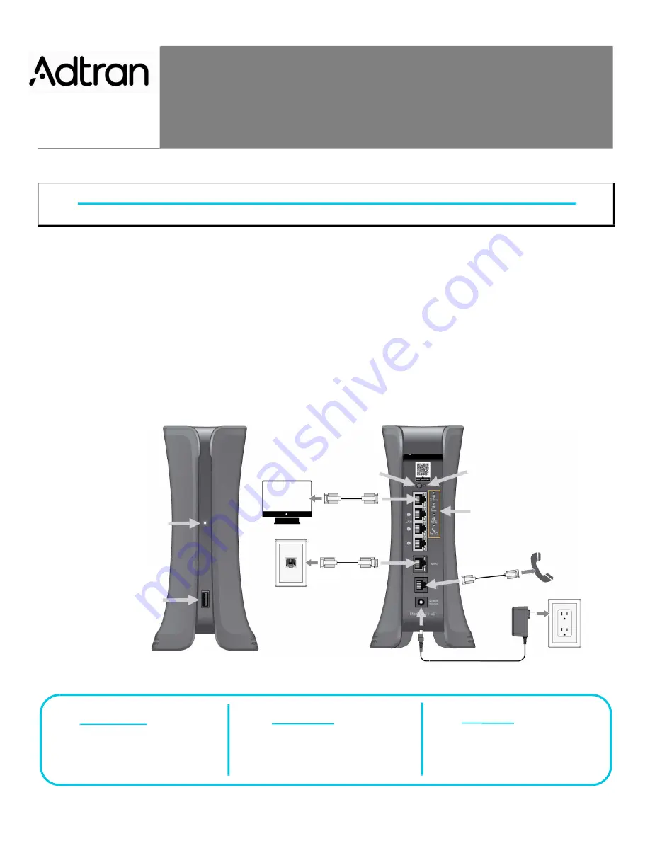
■ 1G WAN interface (RJ-45)
■ 4x 1G LAN interface (RJ-45)
■ POTS interface (RJ-11)

This quick start describes how to install and connect to the device. 

“Installing the 834-v6 Gigabit Router” 

on page 2

“Understanding the Status LEDs” 

on page 3

“Logging Into the 834-v6” 

on page 5

“Product Specifications” 

on page 5

“Safety and Regulatory” 

on page 6

Figure 1. 834-v6 Gigabit Router

WARNING!

f

Read all warnings, cautions, notes and installation instructions before installing or servicing this equipment.

Multi-function 

Status LED

USB Port

WPS Button

Reset Button

Status LEDs

f


WARNING!

f


CAUTION!

g

     NOTE

WARNING indicates a hazard which, if 

not avoided, could result in death, injury 

or serious property damage.

CAUTION indicates a hazard which, if not 

avoided, could result in service interruption, 

damage to the equipment, or minor property 

damage.

NOTES inform the user of additional, but 

important, information or features.

834-v6


Service Delivery Gateway

Wi-Fi 6 Gigabit Router

September 2022

6SDG834V6-13A

P/N: 17600023F1, 17600023F2, 17600023F3, 17600023F4

Summary of Contents for 834-v6

Page 1: ... Specifications on page 5 Safety and Regulatory on page 6 Figure 1 834 v6 Gigabit Router WARNING f Read all warnings cautions notes and installation instructions before installing or servicing this equipment Multi function Status LED USB Port WPS Button Reset Button Status LEDs f WARNING f CAUTION g NOTE WARNING indicates a hazard which if not avoided could result in death injury or serious proper...

Page 2: ...OTE g Refer to the national state and local electrical codes for the requirements for power grounding wiring and installation methods CAUTION f The product is intended for indoor use only Ethernet and attached equipment are intended for use within the same building with equipotential bonding and not intended to be placed in separate buildings or structures Failure to deploy as described could resu...

Page 3: ...ice to factory defaults press the Reset button for 5 seconds or more Activating WiFi Protected Setup WiFi Protected Setup WPS is a standard means for creating secure connections between the 834 v6 and various wireless client devices This feature is designed to simplify the pairing process between the devices Perform the following steps to activate WPS 1 Press the WPS button on the back of the 834 ...

Page 4: ...e device Confirm whether your 834 v6 is deployed with SmartOS firmware or PlumeOS firmware then choose accordingly from the following options Table 3 Multifunction Status LED for PlumeOS Color LED State Event Blue Solid Power On Green Pulsing Attempting to Connect Green Blinking double During device naming this device and waiting for optimization to finish N A Off During device naming other device...

Page 5: ...uring the quick setup 5 Select Sign In The Dashboard page appears showing data about the system Using PlumeOS When running PlumeOS all settings are configured through either the HomePass smartphone app customers or the Frontline app in the Plume portal ISP s HomePass can be found in both the Google and Apple app stores Frontline is located in the Plume portal at https portal plume com home Product...

Page 6: ...ting up outdoor radio links in France and in some areas the RF output power may be limited to 10 mW EIRP in the frequency range of 2454 2483 5 MHz For detailed information the end user should contact the national spectrum authority in France CAUTION f Connect the DC power input to an approved Limited Power Source LPS power supply ONLY This product is intended to operate in ambient temperatures up ...

Page 7: ... equipment does cause harmful interference to radio or television reception which can be determined by turning the equipment off and on the user is encouraged to try to correct the interference by one or more of the following measures Reorient or relocate the receiving antenna Increase the separation between the equipment and receiver Connect the equipment into an outlet on a circuit different fro...

Page 8: ...point operation as appropriate iv the worst case tilt angle s necessary to remain compliant with the e i r p elevation mask requirement set forth in Section 6 2 2 3 shall be clearly indicated v Users should also be advised that high power radars are allocated as primary users i e priority users of the bands 5250 5350 MHz and 5650 5850 MHz and that these radars could cause interference and or damag...

Reviews: