background image

| 11

Transducer installation | 

Installation Manual

Forward:

Use for seeing fish and structure directly in front of the transducer. 

Know the depth of the fish and structure to target your next cast. 

Scout:

Use to scan large areas for fish and structure. Search for schooling 

fish and know the direction of your next cast. 

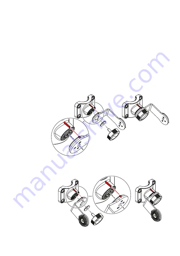
Attach the bracket arm to the shaft front collar

Install the bracket arm in the desired position to the shaft collar. 

When installed, the arm can be used as a handle to align the shaft 

clamp with the centerline of the trolling motor.

Port side - Down/Forward orientation

Starboard side - Down/Forward orientation

Summary of Contents for ActiveTarget

Page 1: ...ActiveTarget INSTALLATION MANUAL ENGLISH www lowrance com ...

Page 2: ......

Page 3: ...MAY VIOLATE THE LAW This manual represents the product as at the time of printing Navico Holding AS and its subsidiaries branches and affiliates reserve the right to make changes to specifications without notice Governing language This statement any instruction manuals user guides and other information relating to the product Documentation may be translated to or has been translated from another l...

Page 4: ...communications Electromagnetic Compatibility standard 2017 Trademarks Reg U S Pat Tm Off and common law marks Visit www navico com intellectual property to review the global trademark rights and accreditations for Navico Holding AS and other entities Navico is a trademark of Navico Holding AS Lowrance is a trademark of Navico Holding AS ActiveTarget is a trademark of Navico Holding AS About this m...

Page 5: ...lines 9 Installation 10 Transducer installation 10 Shaft mounting 16 Motor mounting 20 Wiring 20 Guidelines 21 Wiring overview 22 Transducer 23 Ethernet 24 Power 27 Grounding 27 LED indicators 28 Dimensional drawings 28 Sonar module 29 Transducer 30 Technical specification 30 Sonar module 31 Transducer ...

Page 6: ...6 Parts included Installation Manual Parts included 1 R T P Q U O S P Q G H J K L M I N A B D E F C ...

Page 7: ...aft collar back shaft mount I Rubber collar inserts 2x J Trolling motor shaft collar front shaft mount K M6 nut 4x L Trolling motor bracket arm shaft mount M M6 metal washers 2x N Transducer arm knobs 2x O Hose clamp P M6x20 cap screw 2x Q M6 metal washer 2x R Trolling motor scout arm motor mount S M6 nut T Trolling motor scout mounting bracket motor mount U Trolling motor down forward mounting br...

Page 8: ...ight be submerged or exposed to moisture Mount any part where it will interfere with the operation launching or retrieving of the boat Mount in a way so that moisture or condensation water can follow the cables into the device Do Consider the overall width and height requirements Leave sufficient clearance to connect all relevant cables Check that it is possible to route cables to the intended mou...

Page 9: ...lation Installation Manual Installation Mark the screw locations using the module as a template and drill pilot holes Secure the module using fasteners that are suitable for the material you are mounting the module to 1 2 3 ...

Page 10: ...he motor of the trolling motor Shaft mounting The transducer can be oriented in three different ways down looking forward looking or in scout position Down Forward Scout The transducer can be mounted on the port or starboard side of the shaft Port side Starboard side Down Use for vertical fishing to see what is below the transducer Watch your lure and fish movements in real time 3 ...

Page 11: ...n large areas for fish and structure Search for schooling fish and know the direction of your next cast Attach the bracket arm to the shaft front collar Install the bracket arm in the desired position to the shaft collar When installed the arm can be used as a handle to align the shaft clamp with the centerline of the trolling motor Port side Down Forward orientation Starboard side Down Forward or...

Page 12: ...12 Transducer installation Installation Manual Scout orientation Align and attach the shaft clamp Align the shaft bracket with the centerline of the trolling motor ...

Page 13: ... 13 Transducer installation Installation Manual Down orientation ...

Page 14: ...14 Transducer installation Installation Manual Forward orientation ...

Page 15: ... 15 Transducer installation Installation Manual Scout orientation ...

Page 16: ... port or starboard side of the shaft Port side Starboard side Down Use for vertical fishing to see what is below the transducer Watch your lure and fish movements in real time Forward Use for seeing fish and structure directly in front of the transducer Know the depth of the fish and structure to target your next cast Scout Use to scan large areas for fish and structure Search for schooling fish a...

Page 17: ...ducer Secure the assembly to the motor using the hose clamp The hose clamp should be tightened just enough to prevent the transducer from moving during normal use Then orient the transducer to the down orientation by firmly gripping and rotating the transducer until the alignment marks are aligned ...

Page 18: ...ucer Secure the assembly to the motor using the hose clamp The hose clamp should be tightened just enough to prevent the transducer from moving during normal use Then orient the transducer to the forward orientation by firmly gripping and rotating the transducer until the alignment marks are aligned ...

Page 19: ...ch the transducer to the scout bracket arm Then install the transducer and bracket arm to the bracket Secure the assembly to the motor using the hose clamp The orientation can be adjusted by firmly gripping and rotating the transducer until the alignment marks are aligned ...

Page 20: ...mechanical systems Run cables over sharp edges or burrs Do Make drip and service loops Use cable ties on all cables to keep them secure Solder crimp and insulate all wiring connections if extending or shortening the cables Leave room adjacent to connectors to ease plugging and un plugging of cables Warning Before starting the installation be sure to turn electrical power off If power is left on or...

Page 21: ... 21 Wiring Installation Manual Wiring overview Transducer Ethernet Sonar module MFD Grounding Battery _ ...

Page 22: ... be adjusted to all possible orientations Forward Down Scout There also needs to be enough slack in the cable loop so that the motor shaft can spin all the way around without damaging the cable Connect the transducer to the sonar port of the module Make sure that the cable is properly supported ...

Page 23: ... 23 Wiring Installation Manual Ethernet Connect the Ethernet cable to the Ethernet port of the module The other end should be connected to your display unit or Ethernet expansion device Ethernet ...

Page 24: ...d fuse rating refer to Technical specification on page 30 The yellow wire in the power cable is used to control how the unit is turned on and off The blue wire should not be used Warning The positive supply wire red should always be connected to DC with a fuse or a circuit breaker closest available to fuse rating Power controlled by external switch The unit will turn ON OFF when power is applied r...

Page 25: ...sory wake up Yellow C 12 V DC Red D DC Negative Black E Fuse F Switch Power controlled by power bus display unit The unit will turn ON OFF when power is applied removed By connecting the yellow wire to a display unit s yellow wire the sonar module will turn on the moment the display unit is powered up ...

Page 26: ...26 Wiring Installation Manual _ A 12 24V DC B E C D Key Description Color A Not used Blue B Accessory wake up Yellow C 12 V DC Red D DC Negative Black E Fuse ...

Page 27: ...can be the vessel s bonded ground earth non bonded RF Ground or battery minus DC negative It is recommended to use a 4 mm2 12 AWG or thicker wire Note No DC power will flow through the connected conductor LED indicators The LEDs on the sonar module indicate the status of the module LED Description Power Solid green during power up When started the led will alternate between green and red Ethernet ...

Page 28: ...28 Dimensional drawings Installation Manual Dimensional drawings Sonar module 72 9 mm 2 86 219 3 mm 8 63 197 3 mm 7 76 175 1 mm 6 89 115 48 mm 4 54 192 1 mm 7 56 5 ...

Page 29: ... 29 Dimensional drawings Installation Manual Transducer 58 0 mm 2 28 149 8 mm 5 90 7 62 m 25 ft 82 4 mm 3 24 ...

Page 30: ...torage temperature 30 C to 70 C 22 F to 158 F Operating temperature 15 C to 55 C 5 F to 131 F IP class IP67 Electrical Power supply 12 24 V DC Operating voltage 10 8 V DC 31 2 V DC Current drain maximum 1 5A at 13 8 V Reverse polarity protection Yes Fuse rating 3 A Physical Weight 1 86 kg 4 12 lbs 6 ...

Page 31: ...onmental Storage temperature 30 C to 70 C 22 F to 158 F Water temperature for operation 0 C to 35 C 32 F to 95 F Physical Weight 1 21 kg 2 67 lbs Cable length 7 62 m 25 ft Mounting options Trolling motor shaft Trolling motor lower unit Transom mount sold separately ...

Page 32: ......

Page 33: ...12797 001 www lowrance com Reg U S Pat Tm Off and common law marks Visit www navico comintellectual property to review the global trademark rights and accreditations for Navico Holding AS and other entities ...

Reviews: