


Lowell UPS8 Series Manual
Pg. 8
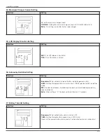
Set Up the UPS
Step 1:
UPS Input Connection .
Plug the UPS into a two-pole, three-wire, grounded receptacle only . Avoid using extension cords .
Step 2:
UPS Output Connection .
There are two kinds of outputs: programmable outlets and general outlets . Connect non-critical devices to the programmable
outlets and critical devices to the general outlets . During power failure, you may extend the backup time to critical devices by
setting shorter backup time for non-critical devices .
Step 3:
Communication Connection .
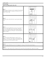
Communication ports:
• USB Port or RS-232 Port: To allow for unattended UPS shutdown/start-up and status monitoring, connect the communication
cable, one end to the USB/RS-232 port and the other to the communication port of your PC . With the monitoring software
installed, you can schedule UPS shutdown/start-up and monitor UPS status through the PC .
NOTE: USB port and RS-232 port can’t work at the same time.
• Intelligent Slot: The UPS is equipped with an intelligent slot ideal for either an SNMP or Dry Contact/Relay card . When
installing either an SNMP or Dry Contact/Relay card in the UPS, it will provide advanced communication and monitoring
options .
Step 4:
Surge Protection .
Connect a single modem/phone/fax line into surge-protected “IN” outlet on the back panel of the UPS unit . Connect from “OUT”
outlet to the equipment with another modem/fax/phone line cable .
Step 5:
Disable and Enable EPO Function .
Keep the pin 1 and pin 2 closed for UPS normal operation . To activate EPO function, cut the wire between pin 1 and pin 2 .
Fax/Phone Surge Port
It’s in closed status for UPS normal operation.


