background image

Lowell UPS8 Series Manual

Pg. 28

APPENDIX A:  External Battery Pack (Model UPS-XBP-48, UPS-XBP-72)

Important Safety Instructions

Please comply with all warnings and operating instructions in this manual strictly . Save this manual properly and read carefully 
the following instructions before installing the unit . Do not operate this unit before reading through all safety information and 
operating instructions carefully .
•  Do not try to repair the unit yourself, contact your local supplier or your warranty will be void . 
•  To eliminate any overheating of the battery box, keep all ventilation openings free from obstruction and do not place any for-

eign objects on top of the battery bank . Keep the battery box 8 inches (20cm) away from the wall . 

•  Make sure the battery box is installed within the proper environment as specified . (0-40°C and 30-90% non-condensing hu-

midity)

•  Do not install the battery box under direct sunlight .  Your warranty will be void if the batteries fail due to overheating .
• This battery box is not designed for use in dusty, corrosive and salty environments . 
•  The warranty for this battery bank will be void if water or other liquid is spilled or poured directly onto the battery box . Similarly 

we do not warrant any damage to the battery box if foreign objects are deliberately or accidentally inserted into the battery 
box enclosure . 

• The battery will discharge naturally if the system is unused for a period of time .
•  It should be recharged every 2-3 months if unused . If this is not done, then the warranty will be null and void .  During normal 

operation, the batteries will automatically remain in charged condition . 

•  Servicing of batteries should be performed or supervised by trained personnel with knowledge of batteries and the required 

precautions . 

• When replacing batteries, it is necessary to replace ALL batteries with the same quantity, type & capacity .
• 

CAUTION –

 Do not dispose of battery or batteries in a fire . The battery may explode .

•  

CAUTION – 

Do not open or mutilate the batteries . The electrolyte from the batteries is toxic and harmful to the skin and eyes . 

•  

CAUTION – 

Risk of Electric Shock –Hazardous voltage may exist between battery terminals and ground . Test before touching 

with bare hands .

•  

CAUTION – 

A battery can present a risk of electrical shock and high short circuit current .  The following precautions should 

be observed when working on batteries:


– Remove watches, rings, and other metal objects .


– Use tools with insulated handles .


– Wear rubber gloves and boots .


– Do not lay tools or metal parts on top of batteries .


– Disconnect charging source prior to connecting or disconnecting battery terminals .

• Do not plug or unplug the battery connector if UPS works in DC (discharging) mode .

Summary of Contents for UPS8-1100

Page 1: ...UPS8 Series Pure Sine Wave Line Interactive UPS Models UPS8 1100 UPS8 1500 UPS8 2000 UPS8 2200 UPS8 3000 User Installation Manual 04 03 18...

Page 2: ...Button Operation 15 LCD Panel 15 Audible Alarms 17 Abbreviations in LCD Display 17 UPS Setting 18 Operating Mode Descriptions 21 Fault Reference Codes 22 Warning Indicators 22 TROUBLESHOOTING 23 STOR...

Page 3: ...puter to connect the UPS system to the building wiring outlet shockproof outlet Use only VDE tested CE marked power cables to connect the loads to the UPS system When installing the equipment it shoul...

Page 4: ...ries may cause electric shock and have a high short circuit current Please take the precautionary measures specified below and any other measures necessary when working with batteries Remove wristwatc...

Page 5: ...connect to non critical loads 2 Output receptacles connect to mission critical loads 3 AC input 4 Input circuit breaker 5 Network Fax Modem surge protection 6 Emergency power off function connector EP...

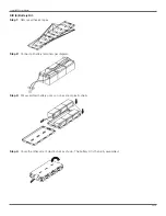
Page 6: ...UPS is shipped out from the factory without connecting battery wires Before installing the UPS follow these steps to re connect battery wires Connect Battery Wires Step 1 Remove front panel Step 2 Co...

Page 7: ...p 2 Attach the mounting brackets to the UPS CAUTION DO NOT use mounting brackets to lift the UPS brackets are only to secure it to the rack Step 3 Place UPS on the support rails and secure in place wi...

Page 8: ...and the other to the communication port of your PC With the monitoring software installed you can schedule UPS shutdown start up and monitor UPS status through the PC NOTE USB port and RS 232 port ca...

Page 9: ...er on the UPS NOTE The battery charges fully during the first five hours of normal operation Do not expect full battery run capability during this initial charge period Step 8 Install software For opt...

Page 10: ...UTION Consider all warnings cautions and notes before replacing batteries Note Upon battery disconnection equipment is not protected from power outages Step 1 Remove front panel Step 2 Disconnect batt...

Page 11: ...Lowell UPS8 Series Manual Pg 11 Step 5 After replacing the batteries return battery box to original location screw tightly Step 6 Re connect the battery wires Step 7 Replace front panel...

Page 12: ...ect battery kit procedure two four or six battery kit listed below to assemble it TWO 2 Battery Kit Step 1 Remove adhesive tapes Step 2 Connect all battery terminals per diagram Step 3 Put assembled b...

Page 13: ...ry Kit Step 1 Remove adhesive tapes Step 2 Connect all battery terminals per diagram Step 3 Put assembled battery packs on one side of plastic shells Step 4 Cover the other side of plastic shell as sh...

Page 14: ...ry Kit Step 1 Remove adhesive tapes Step 2 Connect all battery terminals per diagram Step 3 Put assembled battery packs on one side of plastic shells Step 4 Cover the other side of plastic shell as sh...

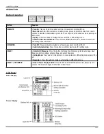
Page 15: ...mode OFF ENTER Turn Off Press and hold this button for at least 2 seconds to turn the UPS off Confirm Selection Key Press this button to confirm selection in UPS setting mode SELECT Switch LCD Messag...

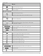
Page 16: ...y or battery voltage V output voltage Hz frequency Load Information Indicates the load level by 0 25 26 50 51 75 and 76 100 Indicates overload Indicates the load or the UPS output is short circuited U...

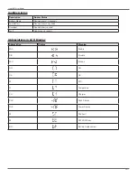
Page 17: ...w Battery Sounds every 2 seconds Overload Sounds every second Fault Continuously sounds Abbreviations in LCD Display Abbreviation Display Meaning ENA Enable DIS Disable ESC Escape ON ON OK OK EP EPO T...

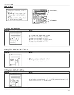
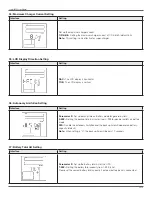
Page 18: ...Programmable outlets enable default DIS Programmable outlets disable Interface Setting Setting the backup time limit in minutes from 0 999 for programmable outlets which connect to non critcal devices...

Page 19: ...99 Setting the backup time in minutes from 0 999 for general outlets on battery mode DIS Disable the autonomy limitation and the backup time will depend on battery capacity default Note When setting i...

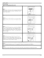
Page 20: ...ng of parameter 2 Press the Up button to change the value to ENA to enable the programmable outlet function Then press Enter button again to confirm the setting Step 4 Press the Up button ON MUTE agai...

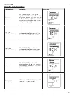
Page 21: ...n the input voltage is higher than the voltage regulation range but lower than high loss point the buck AVR will be activated Boost mode when AC is normal When the input voltage is lower than the volt...

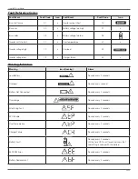
Page 22: ...ery Fault Sounds every 2 seconds At this time UPS is off to remind users that something is wrong with the battery EEPROM Error Sounds every 2 seconds Battery Replacement Sounds every 2 seconds Warning...

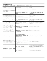
Page 23: ...s shown as 27 and the icon is showing on LCD display and alarm is continuously sounding Battery voltage is too high or the charger is in fault condition Contact your dealer for support Fault code is s...

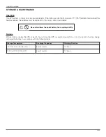
Page 24: ...is case contact your dealer Storage Before storing charge the UPS at least 5 hours Store the UPS covered and upright in a cool dry location During storage recharge the battery in accordance with the f...

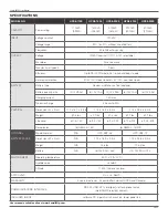
Page 25: ...4 hours to 90 PHYSICAL Dimensions W x D x H 17 2 x 15 1 x 3 5 in 17 2 x 18 9 x 3 5 in 17 2 x 23 6 x 3 5 in Weight 30 5 lbs 44 7 lbs 47 4 lbs 61 7 lbs 67 1 lbs Line cord 6 ft 5 15P 6 ft 5 15P 6 ft 5 20...

Page 26: ...possible help solve the problem over the phone In the event that the unit requires factory service the representative will issue you a Return Material Authorization number RMA If you are returning th...

Page 27: ...or a Lowell Manufacturing Company approved third party b the equipment is damaged by the customer is improperly used or stored is subjected to an adverse operating environment or is operated outside t...

Page 28: ...ery box if foreign objects are deliberately or accidentally inserted into the battery box enclosure The battery will discharge naturally if the system is unused for a period of time It should be recha...

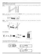
Page 29: ...ws Extended stand 4 point rail kit with screws Selecting Installation Position It is necessary to select a proper environment to install the unit in order to minimize the possibility of damage to the...

Page 30: ...mounting brackets to the unit CAUTION DO NOT use mounting brackets to lift the unit brackets are only to secure it to the rack Step 3 Place unit on the support rails and secure in place with front sc...

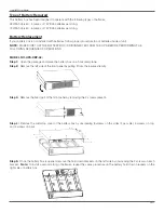
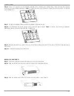
Page 31: ...UENCE OF OPERATIONS MODEL NO UPS XBP 48 Step 1 Open the package and place the battery box on a horizontal plane Step 2 Remove the left side of the front panel by pulling it from the lower extremity St...

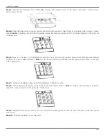
Page 32: ...ries inside and secure in place with hold down brackets Note To install a second string of batteries repeat the same procedure on the right side of battery box Step 9 Replace the metal top cover on th...

Page 33: ...tteries inside the unit by following the drawing below which indicates wire fastener positions for correct battery placement Note To install a second string of batteries repeat the same procedure on t...

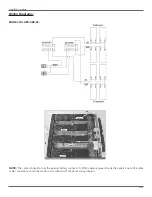
Page 34: ...ing Diagrams NOTE The cable connection from the external battery connector to PCB is already present inside the battery box All the other cable connections should be made in accordance with the above...

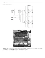
Page 35: ...g 35 MODEL NO UPS XBP 72 NOTE The cable connection from the external battery connector to PCB is already present inside the battery box All the other cable connections should be made in accordance wit...

Page 36: ...se contact your dealer Storage Before storing charge the unit 4 hours Store the unit covered and upright in a cool dry location During storage recharge the battery in accordance with the following tab...

Reviews: