I271
I
GB
F
E
02
17
31100324
G
B
12
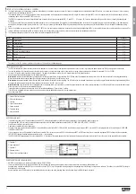
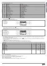
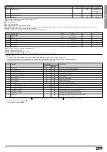
M08 - LIMIT TRESHOLDS UdM Default Range
P08.n.01 Reference measurement OFF OFF- (measures)
P08.n.02 Function Max Max - Min - Min+Max
P08.n.03 Upper threshold 0 -9999 - +9999
P08.n.04 Multiplier x1 /100 - x10k
P08.n.05 Delay sec 0 0.0 - 600.0
P08.n.06 Lower threshold 0 -9999 - +9999
P08.n.07 Multiplier x1 /100 - x10k
P08.n.08 Delay sec 0 0.0 - 600.0
P08.n.09 Normal status OFF OFF-ON
P08.n.10 Latch OFF OFF-ON
Note:
This menu is divided into 8 sections, for limit thresholds LIM1..8
P08.n.01
– Defines which measurements of the multimeter must be compared with limits.
P08.n.02
– Function of the limit threshold.
It can be:
Max
= LIMn active when the measurement is higher than P08.n.03. P08.n.06 is the reset threshold.
Min
= LIMn active when the measurement is lower than P08.n.06. P08.n.03 is the reset threshold.
Min+Max
= LIMn active when the measurement is higher than P08.n.03 or is lower than P08.n.06.
P08.n.03 and P08.n.04
– Used to define the upper threshold, that is made up by the value set in P08.n.03 multiplied by P08.n.04.
P08.n.05
– Trip delay on upper threshold.
P08.n.06, P08.n.07, P08.n.08
– Like above, referred to lower threshold.
P08.n.09
– Allows to invert the status of the limit LIMn.
P08.n.10
– Defines if the threshold remains latched and thus needs to be reset manually (ON) or if it resets automatically (OFF).
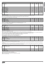
M09 - ALARMS Default Range
P09.n.01 Alarm source OFF OFF-LIMx-INPx-BOOx
P09.n.02 Channel number (x) 1 1-8
P09.n.03 Latch OFF OFF-ON
P09.n.04 Priority Low Low - High
P09.n.05 Text ALAn (Text - 16 char)
Note:
This menu is divided into 8 sections, for alarms ALA1..8
P09.n.01
– Signal that generates the alarm. It can be the overcoming of a limit threshold (LIMx), the activation of an external alarm (INPx), one Boolean logic condition (BOOx).
P09.n.02
– Channel number (x) referred to the previous parameter.
P09.n.03
– Defines if the alarm remains latched and has to be reset manually (ON) or if it automatically resets (OFF).
P09.n.04
– If the alarm has high priority, when it is activated the display page automatically switches on the alarm page, and the alarm is shown with the Warning icon. If instead the priority level is low, the page does
not change and shown with the information icon.
P09.n.05
– Free text of the alarm. Max 16 characters.
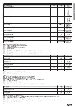
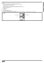
M07 - COMMUNICATION UdM Default Range
P07.n.01 Serial node address 01 01-255
P07.n.02 Serial speed bps 9600 1200
2400
4800
9600
19200
38400
57600
115200
P07.n.03 Data format 8 bit - n 8 bit, no parity
8bit, odd
8 bit, even
7 bit, odd
7 bit, even
P07.n.04 Stop bits 1 1-2
P07.n.05 Protocol Modbus RTU Modbus RTU
Modbus ASCII
Modbus TCP
P07.n.06 IP Address 000.000.000.000 000.000.000.000 -
255.255.255.255
P07.n.07 Subnet mask 000.000.000.000 000.000.000.000 -
255.255.255.255
P07.n.08 IP port 1001 0-9999
P07.n.09 Gateway function OFF OFF/ON
P07.n.10 Client / server Server Client / Server
P07.n.11 Remote IP address 000.000.000.000 000.000.000.000 –
255.255.255.255
P07.n.12 Remote IP port 1001 0-9999
P07.n.13 IP gateway address 000.000.000.000 000.000.000.000 –
255.255.255.255
Note:
this menu is divided into 2 sections, for comm channels COM1..2
P07.n.01
– Serial address (node number) for the communication protocol.
P07.n.02
– Serial communication speed.
P07.n.03
– Data format. Can be set to 7 bits only for ASCII protocol.
P07.n.04
– Number of stop bits.
P07.n.05
– Communication protocol selection.
P07.n.06, P07.n.07, P07.n.08, P07.n.13
–TCP-IP coordinates for application with Ethernet interface. Not used for other types of interface modules.
P07.n.09
– Not supported function.
P07.n.10
– Enabling TCP-IP connection.
Server
= Awaits connection from a remote client.
Client
= Establishes a connection to the remote server.
P07.n.11, P07.n.12
– Coordinates for the connection to the remote server when P07.n.10 is set to Client.


