


EXT
SPKR
SPKR
SPKR
EXT
A B C
C
B
A
SP
Vdc
+12
GND
+
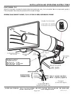
INTERCONNECTION DIAGRAM
LOUROE MODEL AOP-SP70 SPEAKERPHONE CONVERSION UNIT,
AND LOUROE MODEL TLO SPEAKER/MICROPHONE
CONNECTION TO
DVR, IP NETWORK CAMERAS OR VIDEO SERVER
For connection to DVR, IP Network Camera, etc., solder the appropriate plug (RCA, 3.5mm
mono or 3.5mm stereo) to match the audio inputs of the receiving device as shown below.
Refer to IP Camera’s instruction to determine if 3.5mm audio is mono or stereo
Model TLO is Designed For Outdoor
or Moist Applications
WHITE (SP)
BLACK (C)
(C) BARE
(B) RED
TO AUDIO OUT OF DVR, ETC.
TO AUDIO IN OF DVR, ETC.
West Penn 358
or equivalent
BARE (C)
BLACK (B)
RED (A)
WHITE
WIRE NUTS
GREEN
4 Conductor shielded cable
2 shielded 20 gauge and
2 unshielded 18 gauge,
20 gauge drain wire
West Penn 356 or equivalen
t
WIRING REQUIREMENTS FOR TLO
MICROPHONE
CABLE
Microphone connection
using three wire nuts
Red = 12Vdc
Black = Audio Output
Bare = Ground
RED
BLACK
BARE
WHITE SPEAKER
(GROUND)
GREEN SPEAKER
(POSITIVE)
Audio Out
Audio Out
Audio In
Audio In
Bare Wire
Red Wire
RCA CONNECTION
3.5mm MONO CONNECTION
3.5mm STEREO CONNECTION
White Wire
Black Wire
Black Wire
White Wire
Red Wire
Bare Wire
M
O
N
O
S
T
E
R
E
O
Audio Out
Audio In
Red Wire
Black Wire
White Wire
Bare Wire
C
A
SP
B
INSTALLATION AND OPERATING INSTRUCTIONS
Page 5 of 8
LOUROE ELECTRONICS® 6 9 5 5 VA L J E A N AVENUE, VAN NUYS, CA 91406
TEL (818) 994-6498
FAX
994-6458
website: www.louroe.com e-mail: [email protected]
(818)
Using power supply (included), connect as
follows:
Positive 12Vdc connects to terminal marked
“+”
Negative 12Vdc or ground connects to
terminal marked “GND”(wire with white
stripes)
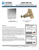
LOUROE MODEL AOP-SP70
aopsp70_ inst_3/15


