LOUD Technologies SR1530z Repair Manual Download Page 6

6

Woofer replacement continued:

  7


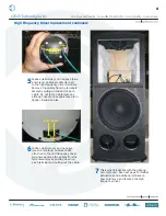
This is what it looks like with the grill and 

woofer removed. Place new woofer 

(part #0013916) where the old one was. 

Follow the same steps as above, but 

backwards 6 to 1, making sure to keep 

the led PCB assembly cable in front of 

woofer. Power up the SR1530z and the 

new woofer should now be pumping 

out glorious lows. Awesome, you just 

replaced a 15” woofer!
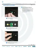
Push 

in

+

-

  6


Remove cables from terminals simply by 

pushing down on terminal and pulling 

out cable.

*

  5


Positive (solid yellow) and negative 

(yellow and black) cables are still 

attached to woofer terminals. 

*

*

These two pictures were taken during an SWA1501 woofer repair. The 

same principle applies to the SR1530z.

Summary of Contents for SR1530z

Page 1: ...1 SR1530z REPAIR MANUAL...

Page 2: ...If available an ESD mat Electro static discharge is optimal Parts needed NOTE not all parts listed below will be needed for your repair Led PCB Assembly Part 0007334 pages 3 4 15 Woofer Part 0013916...

Page 3: ...not fully remove the grill as the cable is still firmly attached to the led PCB assembly 2 Keep the eight screws in a safe place 1 Four screws need to be removed from each side of the grill eight scr...

Page 4: ...the led PCB assembly 6 Carefully remove the led PCB assembly from back side of the grill 7 The hard part is done the rest is easy Place new led PCB assembly part 0007334 where the old one was Follow t...

Page 5: ...en wrench 3 Keep the eight screws and locking washers in a safe place 4 Carefully begin to remove the woofer This woofer has a tendency to want to pop out so please be sure to hold woofer in place wit...

Page 6: ...ble in front of woofer Power up the SR1530z and the new woofer should now be pumping out glorious lows Awesome you just replaced a 15 woofer Push in 6 Remove cables from terminals simply by pushing do...

Page 7: ...ourteen screws need to be removed from the horn using the phillips head screwdriver 3 Keep the fourteen screws and flat washers in a safe place 4 Carefully begin to remove the entire horn assembly wit...

Page 8: ...ugh needle nose pliers may aid in tightly crimped cables Pull out 6 Positive solid green and negative green and black cables are still attached to the mid frequency driver terminals Remove the cables...

Page 9: ...terminals as well 9 Keep the four screws and locking washers in a safe place 10 The high frequency driver easily lifts right off of the horn Replace with the new driver part 0014194 and follow the sam...

Page 10: ...river Notice the placement of the terminals as well 3 Keep the eight screws and locking washers in a safe place 4 The mid frequency driver cover plate easily lifts right off of the horn Positive solid...

Page 11: ...so note that the screws may be tighter than usual Please DO NOT add WD 40 or any other lubricant to help loosen the screws 6 Keep the four screws and locking washers in a safe place 7 The mid frequenc...

Page 12: ...12 Amp Assembly replacement 1 Sixteen screws need to be removed from the amp assembly using the phillips head screwdriver 1 2 3 4 5 6 7 8 9 10 11 12 13 14 15 16 1 2 3 4 5 6 7 8 9 10 11 12 13 14 15 16...

Page 13: ...off yet as seven cables need to be removed first as shown above Each cable must be attached to the same terminal that it was removed from 1 yellow 2 yellow black 3 green 4 green black 5 blue 6 blue bl...

Page 14: ...e again each cable must be attached to the same terminal that it was removed from 1 yellow 2 yellow black 3 green 4 green black 5 blue 6 blue black and 7 led pcb assembly cable white cable next to the...

Reviews: