background image

11 


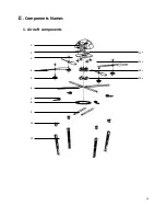
1 Canopy   


8 Conversion Disk          15 Flight Control Board 

2 ESC   


9 cross beam             

3 Propeller Top          10 Locking Block for Landing Gear                   

    4 Propeller  


11 Landing Gear                       

    5 Brushless Motor  

12 Connecting Block #1 

    6 Arm Beam   


13 Connecting Block #2


    7 Locking Block 


14 Connecting Block #3


2. Electronics equipments 

1.


Maximum output current 50A, 4 pcs brushless motor. 

2.


Motor  and  ESC  overload  protection  –  gradual  shutdown  when  ESC 

detects overload condition. 

3.


GPS+INS Combination navigation system. 

4.


Self-stabilized dual axis camera gimbals. 

3. Software system


1.


GPS  software  based  on  Android/iOS,  provides  a  powerful  and  very 

flexible ground control support system. 

2.


All  T600G  with  full  functional  test  and  configured  for  optimum 

performance. 

3.


Ongoing system maintenance and upgrade service support program. 

. Assembly 

All  of  the  T600G  undergo  full  flight  testing  including  full  assembly,  stress  test,  GPS 

Summary of Contents for T600G

Page 1: ...T600G Quadcopter User Manual Version 1 0 June 2013...

Page 2: ...omous flight or experience and emergency IMMEDIATELY switch to manual flight control to avoid any damage to the aircraft or the surroundings in which you are flying 6 Please land the model immediately...

Page 3: ...3 Enjoy your new LotusRC product and always fly safely...

Page 4: ...ponent Names 9 1 Aircraft Components 10 2 Electonic Equipment 11 3 Software System 110 Assembly 11 1 Main Body 120 2 Landing Gear 132 3 Cross Beam Propellers 154 IV Transmitter Receiver Information 18...

Page 5: ...rs we will be able to better service your needs We will pursue all available legal action against those that copy our product or sell it without prior authorization Please contact LotusRC if you have...

Page 6: ...ft has a low drift factor The materials used to build this aircraft are of the highest quality and impact resistant 4 Simple Pre configured with radio control transmitter no setup required 5 Easy to u...

Page 7: ...frame base plate to allow for quick attachment removal from the aircraft The tilt and roll angle can be controlled via the transmitter The new gimbal mounting location helps in the elimination of high...

Page 8: ...Landing Gear Fiberglas Strengthened Aluminum 1 Set 4 Motors C3410 KV420 High Efficiency Out Runner Brushless 4 PCS 5 Propellers 1447 Compounded Industrial Plastic 2 Pairs 6 Camera Gimbals Optional Car...

Page 9: ...S 4250mAh Lipo RX Camera Gimbal 1800g Payload GOPRO DV Light SLR 700g Max Trust With 1P standard LiPo 8800g Max Payload With 1P standard LiPo 1000g Max Takeoff Weight With 1P standard LiPo 2500g Fligh...

Page 10: ...10 Components Names 1 Aircraft components 1 2 3 4 5 6 7 8 9 10 11 12 13 14 15...

Page 11: ...tor 2 Motor and ESC overload protection gradual shutdown when ESC detects overload condition 3 GPS INS Combination navigation system 4 Self stabilized dual axis camera gimbals 3 Software system 1 GPS...

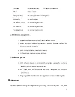
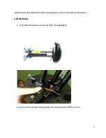
Page 12: ...tdoor test and safety test before packaging to ensure the best performance 1 Main body a In folded mode when removed from the packaging b Press on the corresponding safety pin to release the T600 s 4...

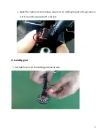
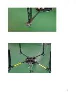
Page 13: ...13 c Open the Carbon arm and press down to the holding mount until you hear a click sound to ensure that it is locked 2 Landing gear 1 Pull out the pins on the landing gear one by one Press the button...

Page 14: ...14...

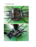
Page 15: ...15 3 Assemble Cross Beam...

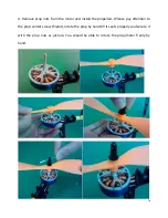
Page 16: ...tor and install the propellers Please pay attention to the prop center screw thread rotate the prop by hand till it seats properly and secure it with the prop nuts as picture You should be able to rot...

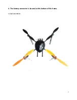
Page 17: ...17 4 The battery connector is located at the bottom of the frame Completed Model...

Page 18: ...in the switch The default is manual mode position hold and auto landing Following a list of common transmitters and their receivers No Brand Transmitter receiver Note 1 Futaba FF9 R149DP 2 JR DSX7 RD...

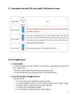
Page 19: ...landing Default landing position is the starting flying position VI Pre flight Check 1 Check Radio 2 Please connect the radio receiver correctly Note 3 gear switch channel is the GPS control wire 3 C...

Page 20: ...ircraft will be at fixed point The experienced flyer could fly it under fixed position directly 5 Auto Landing Transmitter Switch 3 gear flight mode switch to 3 position under position hold mode hover...

Reviews: