INTRODUCTION
Translation of the original instructions
7
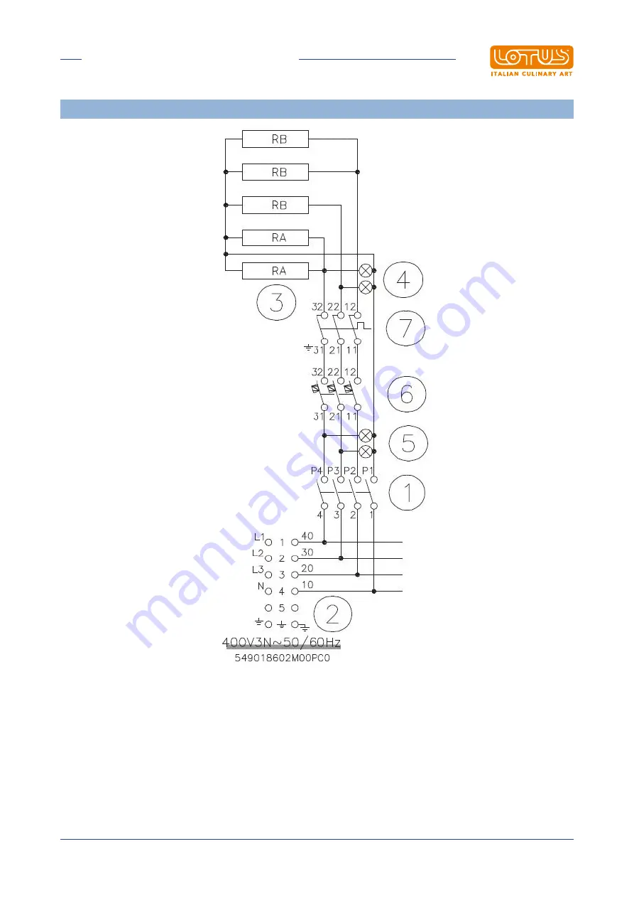
WIRING DIAGRAM OVEN
1 Switch2 Power supply terminal board3 Heating element4 White indicator light5 Green indicator light6 Thermostat7 Safety thermostat
Page 1: ...perating instructions PROFESSIONAL COOKER WITH ELECTRIC OVEN PCQ 558ET PCQ 118ET CFQ4 118ET Model LIBR ISTR PC CF110E Code 5630513A0 Review 1 Edition date 06 06 2022 Language English LOTUS S p A Via Calmaor 46 31020 San Vendemiano 39 0438 778020 39 0438 778277 ...
Page 2: ... waste electrical and electronic equipment 10 2 3 Technical data table 10 3 INSTALLATION 12 3 1 Delivery checks 12 3 2 Removing the packaging 12 3 3 Mechanical installation 12 3 4 Electrical gas connections 12 4 INSTRUCTIONS FOR USE 14 4 1 General information 14 4 2 Lighting and adjusting the open rings 14 4 3 Turning on and adjusting the static oven 15 5 MAINTENANCE 16 5 1 Routine 16 5 2 Spare pa...
Page 3: ...INTRODUCTION Translation of the original instructions 3 1 INTRODUCTION 1 1 Installation drawing FIG 1 PCQ 558ET A Data Plate B Electrical connection ...
Page 4: ...INTRODUCTION Translation of the original instructions 4 FIG 2 PCQ 118ET A Data Plate B Electrical connection FIG 3 CFQ4 118ET A Data Plate B Electrical connection ...
Page 5: ...INTRODUCTION Translation of the original instructions 5 WIRING DIAGRAM PCQ 558ET 1 Power supply terminal board 2 Switch 3 Electrical plate 4 White indicator light ...
Page 6: ...INTRODUCTION Translation of the original instructions 6 WIRING DIAGRAM PCQ 118ET CFQ4 118ET 1 Power supply terminal board 2 Switch 3 Electrical plate 4 White indicator light COMMUTATION ...
Page 7: ...UCTION Translation of the original instructions 7 WIRING DIAGRAM OVEN 1 Switch 2 Power supply terminal board 3 Heating element 4 White indicator light 5 Green indicator light 6 Thermostat 7 Safety thermostat ...
Page 8: ...INTRODUCTION Translation of the original instructions 8 1 2 Example installation of the appliance ...
Page 9: ... electrical safety of this equipment is only ensured when it is correctly connected to an effective ground earth system as required by current electrical safety standards The manufacturer cannot be held liable for any damage caused if the system is not connected to ground earth Before carrying out any cleaning or maintenance tasks on the equipment unplug it from the electricity mains In the event ...
Page 10: ...n health may be due to the misuse of the same equipment or parts of it The symbol next to the rating plate indicates the obligation of separate collection The penalties provided for in the event of improper disposal of RAEE Waste Electrical and Electronic Equipment are those provided for by the national transpositions of European Directives 2012 19 EU 2 3 Technical data table Technical data table ...
Page 11: ...L INFORMATION Translation of the original instructions 11 DESIGN ASSEMBLY TRANSFORMATION ELECTRICAL LINKING TERMINAL BLOCK PERNIONS see technical data table POWER SUPPLY CONNECTION HEATING ELEMENT CONNECTION ...
Page 12: ... not install the appliance near equipment machines used in cold processes If the appliance has to be installed close to cold process equipment it is advisable to install non combustible thermal insulating material and or neutral elements between them 3 4 Electrical gas connections Before being offered for sale on the market the appliance was subjected to gas and electrical testing as required The ...
Page 13: ... of it so that the device can be fully disconnected from the mains this device must have a contact aperture of at least 3 mm The connection terminal is located behind the rear wall Proceed as follows to install the power supply cable Remove the rear panel Pass the new connection cable through the cable gland connect the leads to the corresponding terminal on the terminal block and fasten them secu...
Page 14: ...r a sufficient time for it to cool before carrying out any cleaning or maintenance operation 4 2 Lighting and adjusting the open rings On the front panel a plate is indicated above the knob to which it corresponds marked by the index Turn on the switch located upstream of the appliance Turn the control knob that corresponds to the plate from O to the desired heating level between 1 and 6 The indic...
Page 15: ...t have a smooth bottom with a diameter suitable for the plate never smaller 4 3 Turning on and adjusting the static oven Turn the control knob to the right and set the desired temperature Also turn the knob of the selector setting one of the three positions Top bottom heating element Bottom heating element Top heating element ...
Page 16: ...ce and its safety systems Warning For maintenance replacement of components order and use only original spare parts Replacing parts must exclusively be performed by authorised and or qualified personnel When replacing the electrical components of the machine and the electrical panels scrupulously follow the technical characteristics for the replacement component indicated on the component itself T...
Page 17: ...t fasten the switch regulator to the panel remove all the electrical connections and proceed with replacement HEATING ELEMENT PLATE remove the panel and remove the wires connecting the heating element plate Unscrew the supports that fasten the heating element plate to the hob Once removed make the replacement In the case of cooker hobs the plate is removed from the top of the hob and in the case o...
Page 18: ...s are available commercially but a diluted solution of acetic acid can also be used To clean STAINLESS STEEL appliances it is advisable to use detergents specifically formulated for this material For minor cleaning a mild washing up liquid solution may also be used Do not wash the appliance with jets of water under pressure Avoid using detergents containing abrasive powders or bleaches of any kind...