LOTOS LT5000D Manual Download Page 8

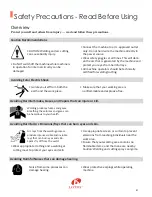
Burn Protection: HOT PARTS can cause serious burns.

Protect eyes from FLYING METAL or DIRT.

PACEMAKERS AND WELDING: MAGNETIC FIELDS can affect implanted devices.

CYLINDER HANDLING: it can explode if damaged.

Welding or Cutting can cause Fire or Explosion. 

If you encounter any difficulties during set up or operation:


• Consult this manual.


• Contact Lotos Customer Service by visiting 

                  http://www.uwelding.com/about-us/contact-us/.

The work piece and equipment 

get hot. The hot metal, hot work 

piece, and hot equipment can 

cause burns.

• Welding, chipping, wire  

   brushing, and grinding cause 

   sparks and flying metal.


Electric arc welding and cutting 

processes produce intense electric 

and magnetic (electromagnetic)

fields. The function of pacemakers 

can be affected by strong 

electromagnetic fields.


Shielding gas cylinders contain gas 

under high pressure. If damaged, 

a cylinder can explode. Be sure to 

treat gas cylinders carefully.


Welding, cutting, and allied 

processes can cause fire or 

explosion if precautionary 

measures are not followed. 


• Use approved helmets or hand shields that 

   provide protection for the face, neck, etc. 

• Wear approved safety goggles or glasses with 

   side shields, even under your helmet. 

• Wear approved safety glasses with side shields, 

   even under your welding helmet. 

• Persons with a pacemaker should not go near 

   welding or cutting operations until they have 

   consulted their doctors and obtained information 

   from the manufacturer of the device.

• Protect compressed gas cylinders from excessive  

   heat, mechanical shocks, physical damage, slag,    

   open flames, sparks, and arcs.

• Install cylinders in an upright position by securing 

   to a stationary support or cylinder rack to prevent 

   falling or tipping.

• Develop adequate procedures, and use  proper   

   equipment to do the job safely. 

• Keep cylinders away from any welding or other  

   electrical circuits.

• Wear dry, hole-free insulated gloves. 

• Remove combustible materials from a sphere  

   with a minimum radius of 35 feet around the 

   work area or move the work to a location well   

   away from combustible materials.

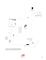
Summary of Contents for LT5000D

Page 1: ... LOTOS TECHNOLOGY Plasma Cutter LT5000D www uwelding com ...

Page 2: ...s from harmful plasma cutting arc radiation Wear safety gloves to protect your hands during operation 2 Connect the machine gas inlet on the back of the machine Figure 1 2 to an air compressor Figure 1 3 1 4 and set the air pressure to 65 70 PSI The air regulator is optional as some air compressors provide air pressure control capability Figure 1 1 Figure 1 2 Power Cord Gas Inlet Gas Inlet Output ...

Page 3: ...utting 5 Change your consumables tip electrode and cup when they become worn out The correct consumable type is LCON The metal protector on the tip is also replaceable All accessories and consumables can be purchased at www uwelding com or Lotos s authorized resellers Thank you for your business 3 Connect your plasma cutting torch and ground cable to the front panel of the machine Figure 1 5 Figur...

Page 4: ... LOTOS Plasma Cutters User Manual Version 2 0 May 2014 copyright Lotos Technology www uwelding com is operated by Lotos Technology ...

Page 5: ...ng Harmful Noises Fire or Explosion Burn Protection Protecting Eyes from Flying Metal or Dirt Pacemakers Cylinder Handling Equipment 6 General Overview Main Characteristics Specifications Adjustor Diagram Power Cord Plug Connection Connecting Cables to Machine Installations Instruction Notes 13 Cutting Environment Safety Notes for Torch Maintenance and Troubleshooting Trouble Shooting Guide Plug W...

Page 6: ...procedures for proper operation of the equipment IMPORTANT Be sure to review the contents of this manual before attempting to operate the equipment This manual should be located where it can be easily referenced by all users of the machine Audience This manual assumes that all individuals reading the manual and using the welder cutter are able qualified and or certified to operate this type of mac...

Page 7: ...es and skin Avoiding Fatal Electric Shock Protect yourself and others from injury read and follow these precautions Welding produces fumes and gases Breathing these fumes and gases can be hazardous to your health 4 Do NOT switch off the machine while machine is in operation for internal circuitry can be damaged Wear appropriate clothing and a welding or cutting mask to protect your eyes and skin U...

Page 8: ...ing cutting and allied processes can cause fire or explosion if precautionary measures are not followed Use approved helmets or hand shields that provide protection for the face neck etc Wear approved safety goggles or glasses with side shields even under your helmet Wear approved safety glasses with side shields even under your welding helmet Persons with a pacemaker should not go near welding or...

Page 9: ... steel alloy steel mild steel copper aluminum and other metal materials there are many applications for plasma cutters Input voltages 110 220V 1 PH 50 60 Hz Input current 110 220V 1 PH 20 A Output current 10 50 A Duty cycle 40 C 104 F 60 50A 110V 60 50A 220V Dimensions with handle 15 381mm L 6 152 4mm W 12 304 8mm H Weight w 8 11 2 7 m torch 22 5 lbs 10 2 kg Gas Supply Clean dry oil free air Recom...

Page 10: ...Shield Cup Swirl Ring Package Type Total Pieces LCON0120 LN01 LE01 LC01 LR01 LN01 x 10 LE01 x 10 20 LCON0140 LN01 LE01 LC01 LR01 LN01 x 10 LE01 x 10 LR01 x 10 LC01 x 10 40 LCON0190 LN01 LE01 LC01 LR01 LN01 x 40 LE01 x 20 LR01 x 20 LC01 x 10 90 LCON0220 LN02 LE02 LC02 LR02 LN02 x 10 LE02 x 10 20 LCON0240 LN02 LE02 LC02 LR02 LN02 x 10 LE02 x 10 LR02 x 10 LC02 x 10 40 LCON0290 LN02 LE02 LC02 LR02 LN0...

Page 11: ... 8 16 50 Stainless Steel 10 gauge 3 50 1 4 6 50 3 8 10 50 1 2 12 50 Aluminum 1 8 3 50 1 4 6 50 3 8 10 50 1 2 12 50 Production cut thickness are the results of Lotos laboratory testing Production speeds are approximately 80 of maximum For optimum cut quality cutting speeds may vary based on different cutting applications ...

Page 12: ...tting Current Adjust Power Air Output Switch Plug Ground Connection Power Cable Gas Inlet Problem Indicator LED Figure 2 1 Adjustor Diagram 9 Figure 2 2 Power Cord Plug Connection Figure 2 3 Air Regulator Configuration ...

Page 13: ... 10 Air Compressor Air Power Output 3 pin Switch Plug Filter Ground Torch Ground Clamp Work Piece Figure 2 4 Connecting Cables to Machine ...

Page 14: ...then tighten 3 Ensure that the air plug of the torch is connected to the switch connector on the panel For cutters with pilot arc connect the fork connector to the red terminal on the front panel 1 Ensure that the cutting machine is properly grounded 2 Ensure that all connectors are connected appropriately and firmly 3 Ensure that power voltages are correct 1 Make sure the machine on off switch is...

Page 15: ...or thicker cutting over a pre drilled pilot hole Press the button on the torch to start cutting 7 Ensure that the cutting current is appropriate and adequate for the machine based on the rated thickness of the cutter Note Below is the consumable assembly on the torch head Figure 3 1 Figure 3 1 cut on off torch body cup seat double sided electrode ceramic ring copper tip ceramic cup ...

Page 16: ...e is reduced to allowable range machine can be operated again 1 Ensure that the copper tip is not in direct contact with the work piece while cutting To protect copper tip torch should be inclined and maintain a distance of 1 mm from inter hole of copper tip to the work piece 2 If pilot arcing functions improperly try to remove oxidization of the electrode on the torch with sand paper 1 Dust creat...

Page 17: ...ot on 1 The nozzle is oxidized or too far away Remove the oxidization on the surface or shorten the distance to 1 mm 2 Otherwise contact the manufacturer or certified service personnel 6 The abnormal pilot light is on 1 Over current protection may have initialized Either wait for 2 or 3 minutes for the problem to go away or turn off the power wait until the abnormal pilot light is off and restart ...

Page 18: ...ines are dark green Some of them are green with a yellow twisted line in them Some of the machines have blue dark green and dark red wires and it may be difficult to differentiate which wire is ground because the blue and dark green looks similar The best way to test for proper ground is to test the ohms between the machine chassis ground to the wire ground Note When ground wire is incorrectly con...

Page 19: ... ...

Reviews: