background image

13

Camera Installation

Camera Installation

Before you install the camera, carefully plan where and how you will position the camera, and 
where you will route the cable that connects the camera to the SHS-4SM switcher.

Installation Warnings: 

• Select a location for the camera that provides a clear view of the area you want to monitor, 

which is free from dust, and is not in line-of-sight to a strong light source or direct sunlight.

• Do not install the camera in a location where it will be 

• Plan the cables’ route so that it is not close to power or telephone lines, transformers, 

microwave ovens or other electrical equipment that could interfere with the system.

• Select a location for the camera that has an ambient temperature between 14

°

F~113

°

(-10

°

C~45

°

C)

• If you plan to install the camera in a location that has conditions not recommended in this 

manual, consult with a professional installer and consider use of a separate camera cover 
or housing

• Before starting permanent installation, have another person hold the camera for you while 

you verify its performance by observing the image on the monitor. 

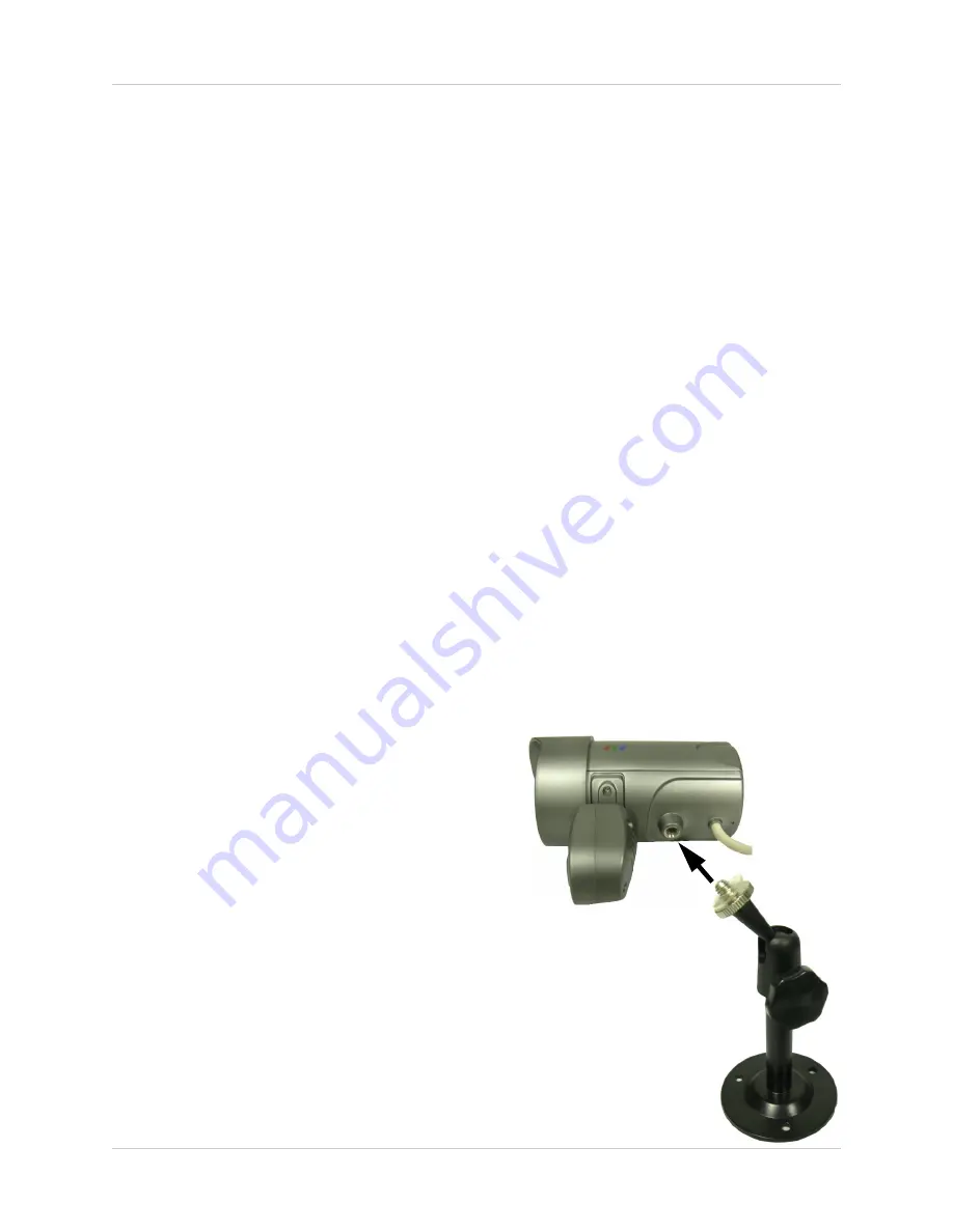
Camera Stand Installation:

1. Attach the pedestal to the ceiling, wall or 

other surface by the base using the 
provided screws.

2. The mounting bracket must be attached to 

a structural device such as a wall stud or 
ceiling rafter using the supplied screws.

3. Attach the camera to the pedestal. Adjust 

the angle of the camera, and tighten the 
thumbscrew to set the position

NOTE

: The Camera can be attached to the stand using the screw point on 

the top or the bottom (to maintain proper camera alignment). This prevents 
the image from becoming inverted.

Summary of Contents for SHS-4SM

Page 1: ...Video Surveillance System with 4 Indoor Outdoor Night Vision Cameras Instruction Manual English Version 1 0 MODEL SHS 4SM Copyright 2006 LOREX Technology Inc www lorexcctv com...

Page 2: ...T FIRE OR SHOCK HAZARD DO NOT EXPOSE THIS UNIT TO RAIN OR MOISTURE CAUTION TO PREVENT ELECTRIC SHOCK MATCH WIDE BLADE OF PLUG TO WIDE SLOT FULLY INSERT Thank you for purchasing the SHS 4SM Lorex is co...

Page 3: ...ord and if its appearance indicates damage or deteriorated insulation have it replaced by your service technician 7 Power Cord Protection Power supply cords should be routed so that they are not likel...

Page 4: ...can prevent fire electric shock or other hazards 16 Safety Check Upon completion of any service or repairs to this video product ask the service technician to perform safety checks recommended by the...

Page 5: ...ted z Consult the dealer or an experienced radio or television technician for assistance LOREX TECHNOLOGY INC http www lorexcctv com NOTE This equipment has been certified and found to comply with the...

Page 6: ...i DIN input for any LOREX CMOS CCD observation camera Easy Setup connects to any TV VCR or Monitor makes this security system perfect for protecting your home family and personal property PIR Motion S...

Page 7: ...tarted 8 SHS 4SM Front View 9 10 SHS 4SM Rear View 11 SHS 4SM Cameras 12 Camera Installation 13 Installation Warnings 13 Camera Stand Installation 13 Connecting Cameras 14 Connecting the SHS 4SM A V C...

Page 8: ...following components CHECK YOUR PACKAGE TO CONFIRM THAT YOU HAVE RECEIVED THE COMPLETE SYSTEM INCLUDING ALL COMPONENTS SHOWN ABOVE Swticher Power Adapter 4 x Weatherproof Color Day Night IR Cameras AV...

Page 9: ...indicator will be ON or flashing to indicate the switcher is in AUTO SCAN mode The AUTO SCAN has a default of 2 seconds per channel To change this setting press and hold the CAM SELECT button for 2 se...

Page 10: ...CAM3 and the CAM SELECT button is pressed the switcher will skip over CAM4 and CAM1 as there are no cameras connected and will display CAM2 4 ALARM DURATION DIAL Sets the Alarm DWELL TIME between 5 an...

Page 11: ...of the cable to the SHS 4SM switcher and the Yellow Video and White Audio plugs to the corresponding terminal on the TV 2 DC 15V Connects the 15V DC Power adapter 3 CAM1 CAM4 DIN INPUTS Connection po...

Page 12: ...deo Audio Power from the SHS 4SM switcher to the Camera STAND Stand connects to the Camera for mounting to walls ceilings and other surfaces INFRA RED LEDs Provides illumination for low light conditio...

Page 13: ...e between 14 F 113 F 10 C 45 C If you plan to install the camera in a location that has conditions not recommended in this manual consult with a professional installer and consider use of a separate c...

Page 14: ...are pointed together when connecting the cable If the pins in the DIN Cable are bent the Camera will NOT function 2 Connect the male end of the supplied 65 extension cable to an open DIN camera input...

Page 15: ...RCA Video and Audio cables to the TV VCR or Monitor Connectivity Diagram TV VCR MONITOR Connect the Yellow AV Cable end to an available video port and the white AV Cable end to an available audio por...

Page 16: ...5 to 30 seconds Scan Time 2 5 or 10 seconds Operating Voltage 15V DC 800mA Camera Input 4 DIN AV Output 1 DIN Camera Specifications Image Sensor Color CCD Input Voltage 12V DC Lens Angle 70 Diagonal R...

Page 17: ...RCA Video and Audio cables to the TV VCR or Monitor Connectivity Diagram TV VCR MONITOR Connect the Yellow AV Cable end to an available video port and the white AV Cable end to an available audio por...

Reviews: