


28
Time Lapse Video Cassette Recorder
27
Time Lapse Video Cassette Recorder
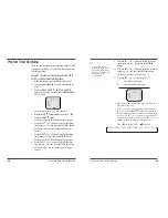
Setting the Security Lock (Set Lock)
The security lock function is designed to prevent
accidental stopping of recording if the STOP button is
pressed inadvertently.
1
Set the SET LOCK switch to “ON” position.
• “
“ is displayed on the display panel.
2
To cancel the security lock, set the SET LOCK switch
to “OFF” position.
• “
“ will be erased from the display panel.
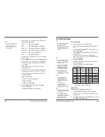
Setting the SW Out Terminal Output
Synchronization pulses for multiplexers can be obtained
from the SW OUT terminal.
1
Press the MENU button, to display the initial MENU.
2
Press the SHIFT
button to move the arrow
mark(
) to SW OUT Terminal Set.
3
Press the SHIFT
button to display the SW OUT
TERMINAL SET menu.
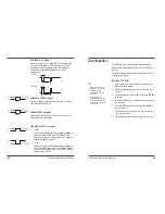
4
Press the SHIFT
button to set “FIELD” (or
“FRAME”).
• With each press of the SHIFT
button, the setting will
changes as indicated below.
5
Press the SHIFT
button, to select Timing.
6
Press the SHIFT
button to set the “TIMING”.
• FIELD . . . 1 pulse is output after each set number of
fields.
• FRAME . . 1 pulse is output after each set number frames.
✔
• While the security lock is
engaged, all commands
are disabled.
• The security lock should
not be engaged while a
menu is displayed.
✔
• If “TIMING” is set to
FRAME (see step 6),
“FRAME” will be indicated
instead of “FIELD”.
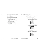
Other Functions
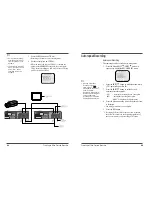
Tape Counter (Zero Search)
Using the counter, it is easy to find a desired recording.
1
Press the CLEAR button, at the beginning of the
desired recording.
• The counter will be reset to “0H 00M 00S” (on screen).
• The counter will be reset to “0H 00M”(on the display
panel).
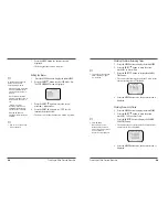
2
After recording or playback, press the Menu button
to display the initial MENU.
3
Press the SHIFT
button to move the arrow mark
(
) to Search Select.
4
Press the SHIFT
button to display the SEARCH
SELECT menu. The SEARCH SELECT menu is
displayed.
5
Press the SHIFT
button to move the arrow mark
(
) to Zero Search.
6
Press the SHIFT
button to search the counter “0H
00M 00S”(“0H 00M” on the display panel).
• The display returns to the normal screen.
• The tape is rewound or advanced to the counter “0H
00M 00S” reading(“0H 00M” on the display panel).
✔
• When you insert a
cassette, the counter
always resets to zero.
• There is no tape counter
indication for the blank
portions of tape.
• In the 2-hour recording
speed mode only, the tape
counter indicates real
hours, minutes and
seconds.
• In the other SP recording
speed modes(24H, 36H),
the tape counter indication
is a ratio of the 2-hour
mode base indication.(In
24-hour recording mode,
each “second” of the tape
counter actually represents
approximately 24/2 =
12 real seconds.)
• In the other EP recording
speed modes(18H), the
tape counter indication is
a ratio of the 6-hour mode
base indication.(In 18-
hour recording mode,
each “second” of the tape
counter actually represents
approximately 18/6 = 3
real seconds.)
• There may be a slight
discrepancy between the
position shown on the
tape counter and the
actual tape position.
• When rewinding the tape
past the “0H 00M 00S”
position(“0H 00M” on the
display panel), a minus(-)
displayed.


