background image

7


Using the display 


Turning on the display 

Turn on the display before turning on the computer. When the power is on, the LED on the power 
button lights blue and the screen image will appear after about 10 seconds. If the LED doesn't 
light blue or no image appears, please verify if the display is properly connected. 


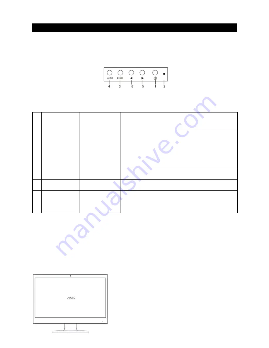
(Figure 4) 
 

Function controls 


1 POWER 

Power 

Switch 

Power ON/OFF 
Blue LED - Power ON mode 
Orange LED - Power saving mode 

2 LED 

Power Indicator


When the monitor is under normal working condition,the 
indicator will light green (or blue);if the monitor is under 
power saving mode ,the indicator will glow red (or 
orange)or off, And the indicator will turn off under the 
power off mode. 

3 MENU 

OSD function 
menu 

OSD off: Displays the OSD function menu 
OSD on: Confirm the OSD function option 

4 AUTO 

Auto adjustment 
button 

OSD off: Perform the auto adjustment function 
OSD on: Exit the OSD function menu 

5 > 

Right/increase 
button 

OSD on: Press this button to select/increase the 
adjustment 

6 < 

Left/decrease 
button 

OSD off: Press this button directly to serve as the 
shortcut for input 
OSD on: Press this button to select/decrease the 
adjustment 


Control of the Touch Function 

Note: 

1.  Before using the touch function, make sure you connect the USB cable from 

the monitor into the USB port on the computer or DVR. The touch applications 
from the CD-ROM must be installed if you are running Windows XP and VISTA. 

2.  When the touch function is active, make sure there are no obstructions on the 

screen. 


(Figure 5) Ensure there are no foreign objects that may come 
in contact with the display. 
The touch function may replace the mouse after you start the 
Windows operating system and introduce appropriate finger 
gesture judgement.   


Summary of Contents for L22LT11B

Page 1: ...1...

Page 2: ...QUALIFIED SERVICE PERSONNEL The lightning flash with arrowhead symbol within an equilateral triangle is intended to alert the user to the presence of uninsulated dangerous voltage within the products...

Page 3: ...www lorextechnology com support If you require further installation assistance please visit www lorextechnology com installation or contact a professional installer Please refer to the Need Help inser...

Page 4: ...euillez constater qu une fois que les com posantes de ce produit ont t retir es de l emballage vous ne pourrez plus retourner ce produit directement au magasi Favor de leer la gu a de instalaci n r pi...

Page 5: ...are for warranty and accessory sales customerservice lorexcorp com Customer Feedback info lorexcorp com Need Help CONTACT US FIRST Online To order accessories visit www lorextechnology com 3 Easy Ways...

Page 6: ...et les ventes d accessoires customerservice lorexcorp com OU 3 maneras sencillas de comunicarse con nosotros Norte Am rica Atenci n al cliente 1 888 425 6739 1 888 42 LOREX Soporte t cnico 1 877 755 6...

Page 7: ...s 5 Packaging procedures 5 Adjusting the viewing angle 5 Connection instructions 6 Using the display 7 Turning on the display 7 Function controls 7 OSD selection 9 OSD Menu 9 Troubleshooting 12 Produc...

Page 8: ...ssories Note Please keep the original carton and packing materials for future transportation or shipment of the display LCD display Power cord Audio cable Signal cable VGA USB cable DVI cable Quick St...

Page 9: ...in the original packaging manner Important Before you start place a clean towel or cloth on a flat surface where you can place the removed display panel without being damaged Adjusting the viewing an...

Page 10: ...cable to the DVI connector on the rear of the monitor and the other end to the DVI connector on the rear of the PC or DVR This is recommended for optimal performance 3 Audio cable Connector one end of...

Page 11: ...on Confirm the OSD function option 4 AUTO Auto adjustment button OSD off Perform the auto adjustment function OSD on Exit the OSD function menu 5 Right increase button OSD on Press this button to sele...

Page 12: ...applications Note Keep the display away from any heat sources such as electric radiators natural gas pipes or direct sunlight Also keep the display away from excessive dust mechanical vibration or sh...

Page 13: ...button to select an option from the 7 functions in the menu Select the function you want to adjust on the OSD function menu and then press MENU to make the adjustment Please use the or button to adju...

Page 14: ...10...

Page 15: ...11...

Page 16: ...the image resumes Abnormal colors are present Please refer to the Color Temperature section to adjust the RGB color or select a color temperature The image bounces or a wave pattern is present Remove...

Page 17: ...cy 24 83 kHz Horizontal 50 76 Hz Vertical Optimum graphic resolution 1920 x 1080 60Hz Max Pixel clock 180 MHZ Tilt 5 20 Audio output 1W X 2 Power supply AC 100 240V 50 60Hz Power consumption Display m...

Page 18: ...14 Touch Screen Specifications...

Page 19: ...VGA 3 800 x 600 37 879 60 317 40 000 VESA 4 1024 x 768 48 363 60 004 65 000 VESA 5 1280 x 720 45 00 60 00 74 25 VESA CEA 861D 6 1280 x 960 60 00 60 00 108 000 VESA 7 1280 x 1024 63 98 60 02 108 000 VE...

Page 20: ...nce 8 B ground 24 pin DVD D display signal cable Pin No Description Pin No Description 1 TMDS Data 2 13 TMDS Data 3 2 TMDS Data 2 14 3 3 5V Power from PC 3 TMDS Data 2 4 Shield 15 Ground Return for 5V...

Page 21: ......

Page 22: ...R14 PROTECT EVERYTHING THAT MATTERS Parking Lot LBC6050 Office LNZ4001 Home LDC6050 Restaurant Home Office LW2902 Add wired or wireless cameras to expand the Envelope of Protection for your business y...

Reviews: