background image

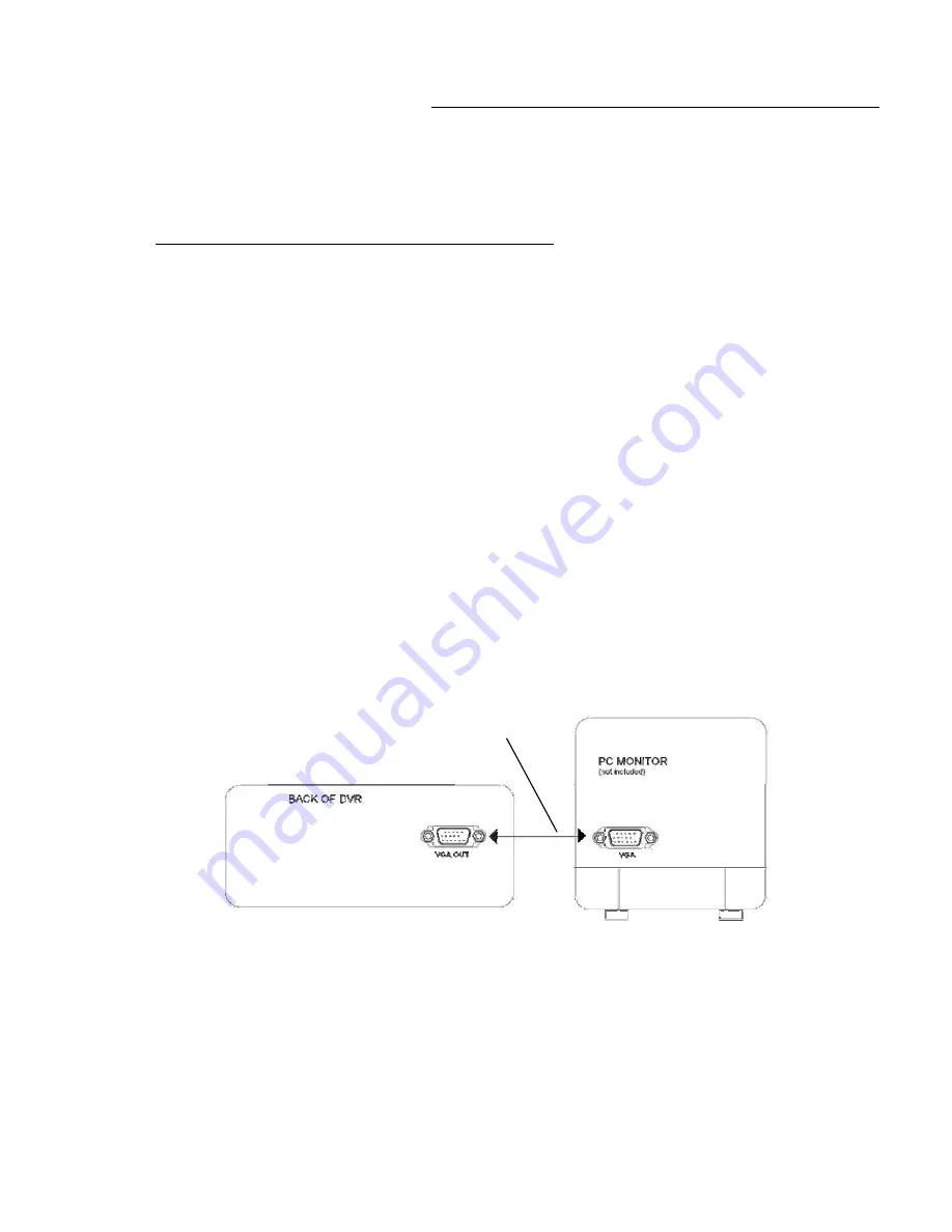
Example 3: Connect a PC monitor (LCD or CRT) to the L174V DVR

1)

Four camera video outputs connect to the four video inputs of the DVR.

2)

The DVR video output (VGA) of a standard PC monitor.  The monitor can be either a 
flat panel LCD or tube style CRT.

3)

Select VGA in the monitor set up selection. 

4)

DVR video output will appear on the PC monitor.

-21-

MONITOR CONNECTION

:

In this type of connection, whatever is visible on the monitor screen will be recorded on the 

DVR.

To view recorded video from the DVR on the monitor

1)

Connect a cable from the DVR video output to the quad monitor video input. The quad 
monitor video input may be labeled on the monitor as VCR video in.

2)

Select VCR on the front panel of the monitor.  You will then be able to view recorded 
video.

VGA Cable (provided with VGA monitor)

Summary of Contents for L164 Series

Page 1: ...64 L174V Series 4 CHANNEL DVR with VGA output L174V only Instruction Manual www lorexcctv com Copyright 2006 Lorex Technology Inc BEFORE OPERATING THIS SYSTEM PLEASE READ THIS MANUAL THOROUGHLY AND RE...

Page 2: ...ECTRIC SHOCK DO NOT REMOVE COVER OR BACK NO USER SERVICEABLE PARTS INSIDE REFER SERVICING TO QUALIFIED SERVICE PERSONNEL Explanation of two Symbols The lightning flash with arrowhead symbol within an...

Page 3: ...s are designed to provide reasonable protection against harmful interference in a residential installation This equipment generates uses and can radiate radio frequency energy and if not installed and...

Page 4: ...ROL CAMERA INSTALLATION MONITOR CONNECTION MONITOR VCR INSTALLATION CONNECT L164 TO A TYPICAL LOREX MONITOR CONNECT L174V TO A TYPICAL LOREX MONITOR TROUBLESHOOTING TECHNICAL SPECIFICATIONS OPTIONAL A...

Page 5: ...of any kind on this product 15 Servicing Do not attempt to service this product yourself as opening or removing covers may expose you to voltage or other hazards Refer all servicing to qualified servi...

Page 6: ...from lightening or power surges 6 Do not try to retrieve the HDD data by PC DVR Features Modified MPEG 5 20Kbyte frame video compression format Recording Frame Rate at 30 fps NTSC Quad mode 7 5fps NT...

Page 7: ...PACKAGE TO MAKE SURE THAT YOU RECEIVED THE COMPLETE SYSTEM INCLUDING THE COMPONENTS SHOWN ABOVE Power Adapter Cord DC 12V 4 5A Optional HDD HDD SCREWS for optional HDD 4 CHANNEL DVR 2 KEYS FOR CARTRID...

Page 8: ...s connected The screen will display LOSS respectively as shown below NOTE 1 If the HDD is not installed correctly or not installed the HDD not found message will appear for 3 seconds and then return t...

Page 9: ...EC Initiates manual recording 6 PAUSE During playback use this button to Pause the video 7 MENU Press the MENU to enter the main menu Please refer to page 8 for more information on the Menu options 8...

Page 10: ...CAMERA SELECT 1 4 Press the Camera Select Buttons 1 4 to select the channel to be displayed in full screen 14 LED INDICATORS Represents the status of operation 1 POWER LED comes on when there s power...

Page 11: ...desired cameras to these inputs 4 VIDEO OUTPUT L164 only Connect the RCA output to display the DVR s Menu and Video Playback L174V only Connect the RCA output to a composite monitor or connect the VGA...

Page 12: ...ur base AM or PM ii DATE FORMAT There are three formats to display the date MM DD YYYY YYYY MM DD or DD MM YYYY 01 01 03 5 00 56 AM MM DD YY HH 00 SS iii DATE Time SET The time and date will be displa...

Page 13: ...Please refer to Appendix 2 for the different recording times iv RECORD QUALITY Sets the quality level of recording Available settings are Low Normal or High Note Higher quality recording consumes more...

Page 14: ...April 2 2005 to 7 50 am for 9 hours and 10 minutes After setting the DAY choose ADD and press the SELECT button Note HH is based on a 24 hour clock 4 RECORD SETTING This submenu allows you to set the...

Page 15: ...9 etc CAMERA SELECT CAMERA 1 ON CAMERA 2 ON CAMERA 3 ON CAMERA 4 ON TITLE ON TITLE SET PRESS cd THEN SELECT PRESS MENU TO EXIT 6 EVENT LOG The event log keeps a record of all errors and alarms that m...

Page 16: ...rd and the confirmation of the password The default user password is 222222 PASSWORD INPUT 6 _ _ _ _ _ _ ADVANCED MENU CHANGE MASTER PASSWORD CHANGE USER PASSWORD MASTER PASSWORD ENABLE OFF USER PASSW...

Page 17: ...is full you will need to clear the space You will be asked to format the HDD HDD FORMAT Y N viii SLAVE HDD CLEAR When the Slave HDD if installed is full you will need to clear the space You will be as...

Page 18: ...ecording OPERATION 1 CAMERA SELECT 1 4 Press Camera Select 1 4 to select the camera to display in full screen 2 RECORDING The DVR offers 3 recording modes listed below Please refer to Appendix 2 for a...

Page 19: ...tarting with the most recent recordings listed first Total Event 15 Move the Pointer to TOTAL EVENT and press the SELECT button to view up to 12 recordings Manual Schedule and Alarm Schedule Rec Event...

Page 20: ...ast Forward up to 4 times the play speed FF1 2x FF2 3x FF3 4x iv STOP Pressing the STOP button will stop all DVR operations and return to the live monitoring mode REW PAUSE FF1 FF2 FF3 SHUTTLE BUTTON...

Page 21: ...rings up the Playback Search mode PLAY Brings up the Main Menu MENU Allows user to select individual cameras 1 4 Displays Quad screen QUAD Initiates Recording REC Pauses video Stops video Playback Fas...

Page 22: ...bed Connect a slave composite monitor Connect a quad composite monitor used as a slave monitor Connect an PC monitor LCD or CRT to the L174V DVR Example 1 Connect a slave composite monitor typical con...

Page 23: ...TOR CONNECTION Example 2 1 Connect a Quad monitor with looping video outputs In this example the quad monitor has individual looping video outputs for each channel 1 Connect the video output from chan...

Page 24: ...he functions of the DVR Example 2 2 Connect a Quad monitor without looping video outputs In this example the quad monitor does not have looping video outputs for each channel A quad monitor without lo...

Page 25: ...R video output will appear on the PC monitor 21 MONITOR CONNECTION In this type of connection whatever is visible on the monitor screen will be recorded on the DVR To view recorded video from the DVR...

Page 26: ...and make it viewable for other parties To record the video signal from your DVR connect an RCA video cable from the Video output on the DVR to the Video input on your VCR 22 MONITOR VCR INSTALLATION O...

Page 27: ...R BACK OF L164 DVR NOTE On Lorex quad monitors the BNC video input channel connectors also support video output The BNC video input output on a Lorex quad monitor can be connected to BNC video input o...

Page 28: ...LOREX MONITOR CONNECTION OF A TYPICAL LOREX OBSERVATION MONITOR TO A L174V DVR BACK OF TFT LCD MONITOR BACK OF L174V DVR NOTE A TFT LCD monitor can be connected through the monitor s video input to th...

Page 29: ...rent password No recorded video Check if the HDD is installed properly Schedule Record enable does not work Check if the Schedule Enable is set to YES Check camera video cable and connections Check mo...

Page 30: ...ng Adaptor 12V 4 5A DC output AC input 20 250 GB Built in Optional On Off ON time is 20 sec Buzzer Out Adjustable Alarm latch up Alarm Dwell Speed Quality variable Alarm Record 1 relay output 3A max N...

Page 31: ...0 hour real time or 1280 hour time lapse VCR SPECIALTY CAMERAS Select from a wide assortment of specialty cameras dome weatherproof bullet waterproof etc to suit individual needs Protects observation...

Page 32: ...Remove the Cartridge Casing from the DVR Lift the Handle and pull towards you The Cartridge Casing will slide out of the DVR Cartridge Casing 1 Keyhole 2 LED indicator lights Power indicator HDD Acces...

Page 33: ...the wider cable is the standard Hard Drive IDE type connection 4 Secure the HDD in the Casing optional Use screws and tighten them positioning the HDD into place This step is optional but it is recomm...

Page 34: ...cabinet by turning the key clockwise A locked B unlocked If you need to unlock the cabinet turn the key counter clockwise from the position shown above IF YOU DO NOT LOCK THE CABINET THE DVR SYSTEM WI...

Page 35: ...ard Disk Drive Internal Drive Bay Accessible through bottom panel Detect the disk capacity of the DVR 1 Connect the DVR to a monitor refer to the monitor connections section 2 Turn the DVR unit on 3 C...

Page 36: ...s based on a 80GB HDD RECORDING QUALITY 1080 hours 144 hours 72 hours 36 hours Quad Screen 1740 hours 232 hours 116 hours 58 hours Quad Screen Full Screen Full Screen 1920 hours 3360 hours 01 FPS 256...

Page 37: ...temperature environment Extreme temperatures can shorten the life of the electronic devices Handle the monitor carefully Dropping it can cause serious damage to the unit Occasionally clean the unit w...

Page 38: ...It s all on the web www lorexcctv com Product Information User Manuals Quick Start Guides Specification Sheets Software Upgrades Firmware Upgrades V I S I T Lorex Technology Inc www lorexcctv com...

Reviews: