background image

Recorder Overview

3

3.1

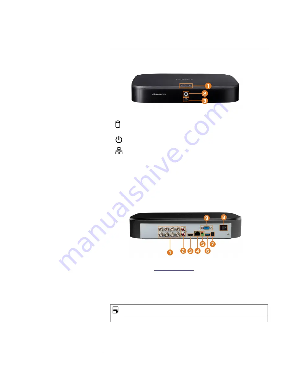
Front Panel

1.

LED Indicators:

HDD:

Glows to indicate hard drive is in normal state. Turns off when there is a hard

drive error.

POWER:

Glows to indicate the system is on.

NETWORK:

Glows when network is in normal state. Turns off when there is a net-

work error.

2.

Info / Panic Button:

From live view, press once to open the System Information screen.

Press and hold for 3 seconds to activate the warning lights and sirens on all connected de-
terrence cameras.

3.

USB Port:

Connect a USB mouse (included) to control the system, or a USB flash drive (not

included) for data backup or manual firmware updates.

3.2

Back Panel

1.

Video Inputs:

Connect Lorex HD or standard analog cameras to the system. For a full list of

compatible cameras, visit

lorex.com/compatibility

.

2.

Audio IN/Audio OUT:

Connect an external microphone for single-channel audio recording,

or an external speaker for system audio. For details on connecting external audio devices, see
18

Connecting Audio Devices

page 87.

3.

HDMI:

Connect to an HDMI monitor or TV (not included) to view the system interface.

4.

LAN:

Connect an RJ45 Ethernet cable for local and remote connectivity.

5.

A/B:

Connect RS485 cables.

NOTE

For full details on connecting PTZ cameras, see 17.1

Connecting PTZ Cameras to the Recorder

page 82.

#LX400111; r. 1.0/55872/56018; en-US

5

Summary of Contents for D841 Series

Page 1: ...User Manual D841 Series...

Page 2: ......

Page 3: ...User Manual D841 Series LX400111 r 1 0 55872 56018 en US iii...

Page 4: ...EFER SERVICING TO QUALIFIED SERVICE PERSONNEL The lightning flash with arrowhead symbol within an equilateral triangle is intended to alert the user to the presence of uninsulated dangerous voltage wi...

Page 5: ...ra Extension Cables 13 6 Using the Mouse 14 7 Using the On Screen Display 15 7 1 Navigation Bar 15 7 2 Quick Menu 15 7 3 Camera Toolbar 16 7 4 On Screen Keypads 17 8 Recording 18 8 1 Video Recording T...

Page 6: ...Listen In Audio 52 14 4 3 Menu Transparency 53 14 4 4 General Display Settings 54 14 4 5 Customize Split Screen Views 54 14 4 6 Configuring Sequence Mode 55 14 5 Camera 56 14 5 1 Adjusting Camera Ima...

Page 7: ...nother Channel 79 15 Connecting Remotely using the Lorex Home Mobile App 80 16 Smart Home Voice Assistance 81 17 Pan Tilt Zoom PTZ Cameras 82 17 1 Connecting PTZ Cameras to the Recorder 82 17 2 Basic...

Page 8: ...7 Special Features 102 22 8 Smart Home 103 22 9 Connectivity 103 22 10 Additional Specifications 103 23 Notices 104 23 1 FCC IC 104 23 2 CE 104 23 3 Modification 104 23 4 RoHS 104 23 5 ICES 003 104 L...

Page 9: ...internal battery that will keep the product running in the event of a power outage CAUTION Maintain electrical safety Power line operated equipment or accessories connected to this product should bea...

Page 10: ...le oper ation of the product and to protect it from overheating These openings must not be blocked or covered The openings should never be blocked by placing the product on a bed sofa rug or other sim...

Page 11: ...sed have the same safety characteristics as the original parts Use of re placements specified by the product manufacturer can prevent fire electric shock or other hazards 4 Safety Check Upon completio...

Page 12: ...ter Ethernet Cable USB Mouse HDMI Cable NOTE Hard drive size number of channels and camera configuration may vary by model Please refer to your package for specific details Check your package to confi...

Page 13: ...e not included for data backup or manual firmware updates 3 2 Back Panel 1 Video Inputs Connect Lorex HD or standard analog cameras to the system For a full list of compatible cameras visit lorex com...

Page 14: ...he system or a USB flash drive not included for data backup or manual firmware updates 7 DC 12V Connect the included power adapter 8 ON OFF Switch Turns the DVR on off 9 VGA Connect a VGA monitor not...

Page 15: ...unting location NOTE Before selecting a permanent mounting location for your cameras see5 Camera Installation page 11 for im portant notes and installation tips The extension cable must be a single st...

Page 16: ...tch the resolution of the connected monitor the first time you use the recorder If you need to switch monitors make sure you set the recorder to an output resolution supported by the new monitor BEFOR...

Page 17: ...Firmware to Latest Version If Available If a firmware upgrade is available you will be asked to install it once the system starts up It is re quired to upgrade your system firmware and client software...

Page 18: ...een can be scanned during mobile setup to enter the system s device ID To quickly open a window that displays important system information From the Live View display right click to open the Quick Menu...

Page 19: ...so that it is not exposed or easily cut Mount the camera in an area that is visible but out of reach Avoid pointing the camera at a glass window to see outside This may result in a bright white ring...

Page 20: ...firm mounting surface that can support the full weight of the camera NOTE If you wish to mount cameras to drywall it is recommended to use the included drywall anchors 2 Adjust the camera stand to en...

Page 21: ...le length refer to your camera s documentation at lorex com 1 Connect the male power connector on the BNC extension cable to the female power connector on the camera Connect the BNC connector to the c...

Page 22: ...mode click an individual channel to view it in full screen Click again to return to the split screen display mode While navigating menus click to open a menu option 2 Right button During live view ri...

Page 23: ...few seconds 5 Playback Opens the Playback Menu This allows you to search for video recordings saved on the recorder s hard drive For details on using the Playback menu see 9 Playback page 23 6 Informa...

Page 24: ...e Mode the system display will automati cally cycle through connected channels every few seconds 8 Disable Beep Temporarily disable the current audible warning NOTE Audible warnings can be given for a...

Page 25: ...cluded 5 Mute Unmute Click to mute unmute listen in audio 6 Warning Light Deterrence Cameras Only Click to manually turn on the camera s warn ing light for 10 seconds 7 Siren Deterrence Cameras Only C...

Page 26: ...nd corner of the camera image when motion is detected 8 2 Configuring Recording Quality The system uses two video recording streams a Main Stream and a Sub Stream The Main Stream records high quality...

Page 27: ...n Frames Per Second FPS that each stream will record at A higher frame rate provides a smoother picture but will require more storage and bandwidth Bit Rate Type Select CBR Constant Bit Rate or VBR Va...

Page 28: ...hedules at once To make fine adjustments to a schedule click This will allow you to set exact start and end times for a schedule To disable all recording of the selected type on the selected day click...

Page 29: ...p The system will not record the Sub Stream for this channel This option is not recommended 4 Under Snapshot select Enable to enable snapshot recording on each channel Or select Dis able to disable sn...

Page 30: ...Recording 8 4 Click Apply LX400111 r 1 0 55872 56018 en US 22...

Page 31: ...t to play back Click the icons to the right of each channel name to choose the video quality for Main Stream for Sub Stream 4 Click inside the video bar to select the playback time The system will beg...

Page 32: ...ngs for the selected date and channel s in list format Fullscreen Shows video in fullscreen Right click to return to split screen viewing 5 Zoom Playback Bar Select the scope of the playback bar 6 Rec...

Page 33: ...recorder in order to hear audio Digital Zoom Click to enable digital zoom Click and drag over the camera image to zoom in on the selected area Right click to return to the full camera image You can t...

Page 34: ...rive not included with video files on it into a free USB port on the recorder 2 From the Live View display right click to open the Quick Menu then click Playback 3 Click the dropdown and select From I...

Page 35: ...elected time 5 Click to configure an area for Smart Search 6 The camera image appears with a grid overlay Click or click and drag to add remove squares from the grid Solid blue areas mark the area of...

Page 36: ...quality for Main Stream for Sub Stream 5 Click inside the video bar to select the playback time The system will begin playing back vid eo from the selected time 6 Click to mark the beginning of the v...

Page 37: ...n the Quick Menu then click Main Menu 2 Click BACKUP 3 Click Format next to the Device Name 4 Select a format mode FAT32 Recommended offers the greatest compatibility with other devices NTFS Advanced...

Page 38: ...software 4 Click Add A list of files that match your search criteria appears 5 Check files you would like to backup 6 Click Backup NOTE HD video files saved on the system may take up a large amount o...

Page 39: ...ols page 32 10 4 2 Viewing Backed Up Files on Mac 1 Download and install the Lorex Player for Mac from the recorder s product page at lorex com 2 Double click the downloaded file in Safari to extract...

Page 40: ...4 3 Lorex Player Controls 1 File List Double click to open a file 2 Viewing Mode Select between single channel viewing and various split screen options 3 Hide Show File List 4 Playback Controls Playb...

Page 41: ...video file to a different format 9 Digital Zoom Click then click and drag over a camera image to zoom in Right click to re turn to the full image 10 Drag Click then click and drag to move around a cam...

Page 42: ...ehicle detection on CAUTION A maximum of 4 channels will support Person Vehicle detection at once By default channels 1 4 have Person Ve hicle detection enabled To configure motion detection 1 From th...

Page 43: ...eal zone selection You can set up to 3 different zones with different sensitivity and threshold values Right click when finished 6 Click Setup next to Schedule to choose which days and times of the we...

Page 44: ...age 61 Record Channel Select the channels that will record when motion is detected on the se lected channel Set the length of recording following a video loss event in the Post_REC field PTZ Activatio...

Page 45: ...etection to enable Person Vehicle detection NOTE See 5 2 Ensuring Accurate Person Vehicle Detection page 11 for important camera installation notes related to channels with Person Vehicle detection en...

Page 46: ...Motion Detection 11 LX400111 r 1 0 55872 56018 en US 38...

Page 47: ...copy function 11 2 Search for Person Vehicle Detection Events Search for Person Vehicle detection on a specific channel or the entire system You can also choose to back up events USB flash drive requ...

Page 48: ...n ually Activate Deterrence Features page 42 For a complete list of compatible deterrence cameras navigate to your recorder series at lorex com compatibility 12 1 Automatic Deterrence Settings Set pre...

Page 49: ...set how quickly the light will flash under Strobe Frequency 6 Click Setup next to Area to set an active area for automatic deterrence The camera image appears with a grid overlay The green area is the...

Page 50: ...atures To activate deterrence features on a single camera Hover the mouse pointer near the top of the camera image in Live View to reveal the Camera Toolbar Click to activate the warning light or to a...

Page 51: ...access to system settings and camera feeds 13 1 1 Changing Passwords You can change the system password of the administrator and user accounts To change an account password 1 From the Live View displ...

Page 52: ...sign what menus they have access to For example you may want your friend to monitor your system while you are away while not giving full access to your system To add a user 1 From the Live View displa...

Page 53: ...ve access to the menus you assigned 13 1 3 Modifying Users Modify account details such as account username or permissions To modify a user 1 From the Live View display right click to open the Quick Me...

Page 54: ...account to have Under the Sys tem tab select the menus the user account may access Under the Playback tab select which channels the user account may access recorded video from Under the Covert tab sel...

Page 55: ...ick OK 13 2 3 Deleting Groups Remove a group To delete a group 1 From the Live View display right click to open the Quick Menu then click Main Menu 2 Click ACCOUNT then click the GROUP tab 3 Click nex...

Page 56: ...as video loss motion detection Person Vehicle detection and system warnings The Alarm menu is also used to set preferences for deterrence cameras 14 2 1 Searching Alarm Event Logs Search all channels...

Page 57: ...Backup 14 2 2 Video Loss Configure video loss settings and how the system reacts to a video loss event Video loss means that video from one or more cameras was interrupted or disabled It could be caus...

Page 58: ...TZ cameras to start a tour pattern or go to a preset location Sequence Sequence mode will begin Select the numbered tiles next to this option to in clude the corresponding channels in the sequence Sna...

Page 59: ...ppear on the recorder s display Buzzer The recorder will sound an audible alarm Send Email Send an email notification with details on the event requires email configura tion see 14 6 3 Configuring Ema...

Page 60: ...ttings 14 4 1 Setting the Recorder s Output Resolution The first time you power up the system and complete the Lorex Setup Wizard the system will au tomatically match the resolution of the connected m...

Page 61: ...ht click to open the Quick Menu then click Main Menu 2 Click DISPLAY then click the DISPLAY tab 3 Check Live Audio 4 Set the desired volume for live audio 5 Click Apply 14 4 3 Menu Transparency Set th...

Page 62: ...o 4 Check to display channel names during Live View 5 Check Original Rate to display 4 3 resolutions e g 5MP in their original proportions 6 Click Apply NOTE You can also adjust where the time and cha...

Page 63: ...rag channels during Live View to change the display order 14 4 6 Configuring Sequence Mode Sequence mode cycles through connected channels to give you an overview of what is happening on all cameras Y...

Page 64: ...nfigured separately see 11 Motion Detection page 34 for details 6 Select a viewing mode to configure It is recommended to start with View 1 and make your way to View 9 By default all viewing modes are...

Page 65: ...k CAMERA Click the RECORDING tab on the side panel then Snapshot on the top panel 3 Under Snap Number select the number of snapshots the system will take when the snapshot button is pressed 4 Configur...

Page 66: ...onfigure 4 Click and drag the blue boxes on the camera image to adjust the location of the date time and channel name 5 Use the checkboxes to enable disable overlays If needed use the text field next...

Page 67: ...ck and drag the edge of a privacy mask to resize it 6 Click Apply 14 5 5 Connecting Multi Format Cameras Cable Type The recorder works with multiple types of HD analog cameras By default the system is...

Page 68: ...ick Main Menu 2 Click CAMERA then click the CVI UPGRADE tab 3 Click Browse to search for the bin firmware file on the USB flash drive 4 Check cameras you would like to upgrade using the selected firmw...

Page 69: ...Configuring System Ports Connection Configure ports used by the system If you are using DDNS connectivity port forwarding is re quired for the HTTP Port default 80 and TCP Port Client Port default 35...

Page 70: ...Using the Main Menu 14 2 Click NETWORK then click the EMAIL tab 3 Click to enable email alerts LX400111 r 1 0 55872 56018 en US 62...

Page 71: ...TP server User Name Enter the SMTP user name Password Enter the SMTP password Email Schedule Click to setup a weekly schedule for email alerts Receiver Select up to 3 email addresses that will receive...

Page 72: ...WORK then click the P2P SETTING tab 3 Click to enable disable P2P connectivity 4 Click Apply 14 7 System Configure general system settings such as date time time zone and DST It also allows you to che...

Page 73: ...e mouse speed 4 Click Apply 14 7 2 Setting Date Time As part of the initial setup you will set the system date time This menu allows you to adjust the date time and configure settings for Daylight Sav...

Page 74: ...e NTP NTP Click to enable disable Network Protocol Time Server Advanced users only Enter a custom NTP server Port Advanced users only Enter a custom NTP port Interval Select how often the system will...

Page 75: ...oliday 5 Click Add 14 7 4 Configuring IP Filter Configure permissions for external IP addresses attempting to access the unit To configure the IP filter 1 From the Live View display right click to ope...

Page 76: ...included to a free USB port on the unit To save system settings 1 From the Live View display right click to open the Quick Menu then click Main Menu 2 Click SYSTEM then click the CONFIG BACKUP tab 3 U...

Page 77: ...display right click to open the Quick Menu then click Main Menu 2 Click SYSTEM then click the DEFAULT tab 3 Check boxes for menus you would like to be reset to default settings or click Factory Defau...

Page 78: ...then click the UPGRADE tab 3 Ensure Automatically Check for Updates is enabled Click Check for Updates to check if a newer version is available 4 If a newer version is found click Upgrade Now to upgra...

Page 79: ...Main Menu 2 Click STORAGE then click the BASIC tab 3 Next to Pack Mode select Time Length for the system to package recording files based on recording length or File Length to package based on file s...

Page 80: ...her channels see 14 11 Copying Settings to Another Channel page 79 for full instructions on us ing the copy function 14 8 4 Setting the Snapshot Schedule You can set a schedule for recording snapshots...

Page 81: ...tings for the current channel to one or more other channels see 14 11 Copying Settings to Another Channel page 79 for full instructions on us ing the copy function 14 8 5 Formatting the Hard Drive If...

Page 82: ...REC Estimate Use the recording calculator to get an estimate of your maximum recording time in days for the in stalled hard drive or how much hard drive space would be required to retain a specific a...

Page 83: ...upports anonymous login Username Enter your FTP username Password Enter your FTP password Remote Directory Enter the directory to save recordings and or snaphsots to File Length Enter the recording fi...

Page 84: ...e Log menu allows you to search for system logs To search for system logs 1 From the Live View display right click to open the Quick Menu then click Main Menu 2 Click INFORMATION then click the LOG ta...

Page 85: ...he network is using the same IP address MAC Conflict More than one device on the network is using the same MAC address Video Loss Shows disconnected channels Motion Shows channels with active motion a...

Page 86: ...1 From the Live View display right click to open the Quick Menu then click Main Menu 2 Click INFORMATION Click the NETWORK tab on the side panel then LOAD on the top panel 14 10 7 Network Test The Tes...

Page 87: ...n click Main Menu 2 Click INFORMATION then click the BPS tab 14 11 Copying Settings to Another Channel Some areas of the main menu allow you quickly copy over the settings from one channel to one or m...

Page 88: ...ows you to View live video from cameras Play back recorded video from the hard drive Manually record video clips or take a snapshot of live video Activate deterrence features including warning lights...

Page 89: ...ve View display right click to open the Quick Menu then click Main Menu 2 Click CAMERA then click the VOICE ASSISTANCE tab 3 Click to enable disable voice assistance 4 Check channels you would like to...

Page 90: ...are using a standard definition PTZ camera you will need to run the camera s RS485 ca bling to the recorder in order to send PTZ commands To connect standard definition PTZ cameras STEP 1 Physical co...

Page 91: ...rent channel to one or more other channels see 14 11 Copying Settings to Another Channel page 79 for full instructions on us ing the copy function NOTE If you copy settings over to connect multiple PT...

Page 92: ...cus on objects closer to the camera Iris Controls the amount of light coming through the lens Click to allow more light or for less 5 Advanced Expand to show advanced options For a full overview see 1...

Page 93: ...tings Not supported 17 4 Presets Presets will save a camera position for quick retrieval To add preset locations 1 From the Live View display of your PTZ camera right click to open the Quick Menu then...

Page 94: ...a in any pattern you wish When finished click End To run a pattern Under No select the number of the pattern you want to go to then click 17 7 AutoScan An autoscan automatically cycles between a left...

Page 95: ...on Channel 1 of the system It cannot be moved to a different channel The second RCA type connector on the back panel is the AUDIO OUT port which can be used to connect a self powered speaker that will...

Page 96: ...HDCVI Click OK 5 Click Apply 6 OPTIONAL Click Copy to apply the settings for the current channel to one or more other channels see 14 11 Copying Settings to Another Channel page 79 for full instructio...

Page 97: ...ng and or use of listen in audio without consent is illegal in certain jurisdictions Lorex Corporation assumes no liability for use of its products that does not conform with local laws Audio Format C...

Page 98: ...size of 10TB 19 1 Removing the Hard Drive CAUTION Make sure that the system is OFF and the power adapter is disconnected before removing installing a hard drive To remove the hard drive 1 Power off th...

Page 99: ...refully then remove the top panel CAUTION The wiring to the front panel button and USB port runs along the top panel of the recorder When separating the top panel rest it carefully beside the bottom p...

Page 100: ...l being mindful of the sharp edges of the bottom panel Remove the hard drive screws 4 from the bottom panel Hold onto the hard drive so it remains in place when all screws have been removed 6 If you a...

Page 101: ...before removing installing a hard drive To install a new hard drive 1 Insert the 2 hard drive screws closest to the SATA and power ports on the hard drive and tight en them half way 2 Power off the s...

Page 102: ...TION The wiring to the front panel button and USB port runs along the top panel of the recorder When separating the top panel rest it carefully beside the bottom panel as shown below 5 Line the 2 half...

Page 103: ...arp edges of the bottom panel Slide the 2 pre inserted screws into the locked position then tighten the screws Insert and tighten the 2 remaining hard drive screws 7 Connect the power and SATA cables...

Page 104: ...ting Remotely using the Lorex Home Mobile App page 80 20 1 STEP 1 Port Forwarding If you are using DDNS you must port forward the HTTP and Client Ports default 80 and 35000 on your router to your reco...

Page 105: ...manufacturer s warranty on your recorder To activate your product warranty 1 From your Lorex account click the WARRANTIES tab 2 Click Activate Warranty 3 Enter your product information attaching bill...

Page 106: ...Add Device Once submitted your DDNS account information will be summarized under My DDNS Devi ces Make a note of your DDNS URL Username and Password as they will be needed to complete DDNS setup 20 5...

Page 107: ...in the DDNS confirmation email 5 Click Apply You will now be able to access your system remotely using DDNS Enter the full domain name into a web browser e g http www tomsmithsecurity lorexddns net an...

Page 108: ...roperly connected Remove the housing and check that hard drive cables are firmly connected There is no hard drive in the system Open the housing and install com patible hard drive Make sure to for mat...

Page 109: ...ces page 87 for details on using audio enabled devices The system beeps during motion detection Motion detection is enabled and the buzzer is activated See 11 Motion Detection page 34 for full instruc...

Page 110: ...splay Live Display Speed Max OSD System Navigation 22 4 Recording Recording Resolution Recording Frame Rate Recording Schedule Back up File Format Video Compression 22 5 Playback Simultaneous Playback...

Page 111: ...TV monitor resolution 2 4K 8MP IP cameras are required to take advantage of 4K recording 3 Person Vehicle Advanced Motion Detection can be enabled only on channels 1 4 General mo tion detection will s...

Page 112: ...interference to radio communications 23 2 CE This product and the supplied accessories are marked with CE and comply with the applicable harmonized European standards listed under Low Voltage Directiv...

Page 113: ......

Page 114: ...er registered trademarks or trademarks of Lorex Corporation and or its subsidiaries All other trademarks trade names or company names referenced herein are used for identification only and are the pro...

Reviews: