Lorex CA453 Instruction Manual Download Page 7

7

Full Connection Diagram

Full Connection Diagram

1. Connect the RED wire to the (12V – 32V DC) power terminal, which powers the system when 

the ignition key is turned on the vehicle.

2. Connect the BLACK wire to a metal portion of the vehicle or the negative battery post.

3. Connect the BROWN wire to the switched power output terminal of the “R” (reverse) gear.

4. Connect the WHITE wire to the Dimmer line.

Operating Instructions

• When you turn the ignition key to the ON position, power is supplied to the monitor. The 

monitor will automatically be in standby mode, even if the Power button is not pushed in.

• When you push the power button you can manually view the picture from the camera(s).

• When the power button is not pushed in, and you shift the gear into reverse, the monitor will 

automatically display the image from selected Camera (if the Auto/Manual switch is in the 
AUTO position).

Summary of Contents for CA453

Page 1: ...Copyright 2007 LOREX Technology Inc www lorexcctv com 5 B W Rear View System Camera Instruction Manual MODEL CA453...

Page 2: ...THIS UNIT TO RAIN OR MOISTURE CAUTION TO PREVENT ELECTRIC SHOCK MATCH WIDE BLADE OF PLUG TO WIDE SLOT FULLY INSERT Thank you for purchasing the Lorex 5 Black White Rear View System Camera This system...

Page 3: ...ted z Consult the dealer or an experienced radio or television technician for assistance LOREX TECHNOLOGY INC http www lorexcctv com NOTE This equipment has been certified and found to comply with the...

Page 4: ...1 8 Lorex CVA453 Accessory Cables Appendix 2 9 CA453 FEATURES Automatic switching of camera when gear is shifted into reverse Built in microphone on camera One way audio Waterproof light sensitive CC...

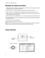
Page 5: ...TEM INCLUDING ALL COMPONENTS SHOWN ABOVE 65 2 Piece Camera Extension Cable 1 3 CCD Weatherproof Camera Camera Installation 1 Connect the 1 8 M cable from the camera to the short 5M piece of the 20M 15...

Page 6: ...a to the desired position make sure the picture is clear and pointed in the correct direction Tighten the screws 5 Drill a cable entry hole through the frame door or window frame just below the mounti...

Page 7: ...R reverse gear 4 Connect the WHITE wire to the Dimmer line Operating Instructions When you turn the ignition key to the ON position power is supplied to the monitor The monitor will automatically be i...

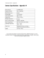
Page 8: ...without incurring any obligation E OE Pick up Device 1 3 B W CCD Number of Pixels 512 x 492 EIA Fixed Focus Lens 2 5mm Viewing Angle 110 Diagonal Horizontal Resolution 380 TV Lines Video Output 1V p p...

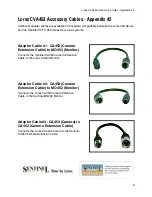
Page 9: ...ystems Adaptor Cable 3 CA453 Camera to CA452 Camera Extension Cable Connects the Lorex CA453 Camera to the Sentinel CA452 Camera Extension Cable Adaptor Cable 2 CA453 Camera Extension Cable to MO452 M...

Page 10: ...It s all on the web Product Information User Manuals Quick Start Guides Specification Sheets Software Upgrades Firmware Upgrades Lorex Technology Inc VISIT wwwlorexcctv com www lorexcctv com...

Reviews: