PROPELLER UPBLAST IO&M
B51071-005
2
Handling
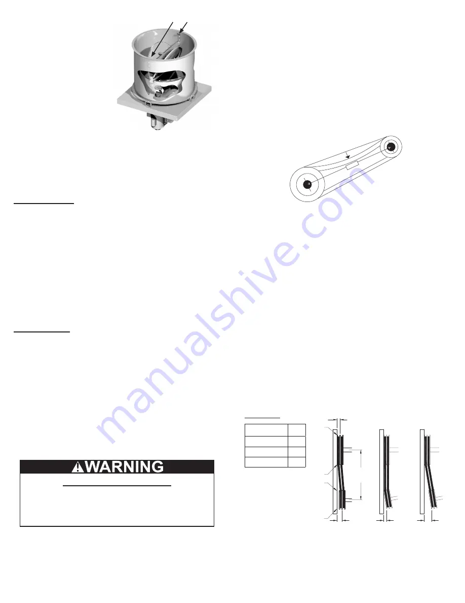
Lift propeller roof ventila-
tors by lifting lugs located in-
side the wind band. Never lift
by the shaft, motor, propeller,
or coupling. If your fan has a
special protective finish, han
-
dle with extreme care. Even
a small chip will break the
coating’s continuity and de-
stroy its ability to protect the
metal. Propellers are carefully
balanced to give smooth, vibration
free operation. If the propeller is dam-
aged during handling, it will require re-balancing.
Storage
If the fan is stored for any length of time prior to installation,
store it in its original shipping crate and protect it from dust,
debris and the weather.
Outdoor Storage
To maintain good working condition of the fan when it is
stored outdoors or at a construction site, follow the additional
instructions below.
• Coat the shaft and bearings with grease or rust preventative
compound to help seal out moisture
• Periodically rotate the propeller and operate the dampers (if
supplied) to keep a coating of grease on all internal bearing
parts
• Periodically inspect the fan to prevent damaging conditions
• Block propeller to prevent natural rotation
• Cover the unit with some type of weather cover to prevent
moisture, corrosion, dirt or dust accumulation
Installation
Damper Installation
1. Place the damper inside the curb. Ensure the damper will
open freely for the correct direction of the airflow.
2. Secure to curb at the damper shelf by installing at least
two sheet metal screws (#10 x 1/2”) on each side of the
damper, through the tray, with the screw head catching
the flange on the damper. This will prevent the dampers
from lifting.
3. Drill a hole in the curb shelf for conduit needed for motor
wiring.
4. Operate the dampers manually to ensure the blades move
freely. Dampers should be released from full open posi-
tion to check for proper closing.
Safety Recommendation
An inlet guard is recommended. An inlet guard prevents
any large debris from being pulled into the fan and damag-
ing the propeller. The inlet guard is installed on top of the
curb prior to the installation of the fan.
Motor Installation
To prevent damage to the fan during shipping, motors 5HP
and larger and extremely heavy motors (cast iron or severe
duty) are shipped loose and must be field mounted.
The motor should be mounted so that the motor plate is
between the fan shaft and motor shaft.
• Remove the motor plate mounting bolts and the motor plate
• Remove the motor mounting bolts from the motor plate
• Mount the motor to the motor plate aligning to the appropri-
ate holes
• Place the motor plate on the power assembly and rein-stall
the mounting bolts
Figure 1
1
foot
1/4
inch
Belt and Pulley Installation
If your fan is a direct drive (models AI, AUD, EUD and TUD),
proceed to
Wiring Installation
.
Belt tension is determined by the sound of the belts when
the fan is first started. The belts will produce a loud squeal,
which dissipates after the fan is operating at full capacity. If
belt tension is too tight or too loose, lost efficiency and dam
-
age can occur.
Do not change the pulley pitch diameter to change tension.
The change will result in a different fan speed.
• Loosen the motor plate adjustment nuts on motor base and
move motor plate in order that the belts can easily slip into
the grooves on the pulleys. Never pry, roll or force the belts
over the rim of the pulley
• Adjust the motor plate until proper tension is reached. For
proper tension, a deflection of approximately 1/4” per foot of
center distance should be obtained by firmly pressing the
belt. Refer to
Figure 1
• Lock the motor plate adjustment nuts in place
• Ensure pulleys are properly aligned. Refer to
Figure 2
Tolerance
Center
Distance
Max.
Gap
Up through 12” 1/16”
12” through 48 1/8”
Over 48
1/4”
OFFSET
ANGULAR
OFFSET/ANGULAR
A
W
X
Y
Z
B
CENTER
DISTANCE
(CD)
GAP
GAP
Pulley Alignment
Pulley alignment is adjusted by loosening the motor pulley set-
screw and by moving the motor pulley on the motor shaft.
Figure 2
indicates where to measure the allowable gap for
the drive alignment tolerance. All contact points (indicated by
WXYZ) are to have a gap less than the tolerance shown in the
Lifting Lugs
Figure 2


