Lord MicroStrain WSDA-200-USB User Manual Download Page 10

WSDA

®

-200-USB

User Manual

2.3

Gateway USB Communication

Drivers for the USB gateways are included the SensorConnect software installation.  With the

software installed, the USB gateway will be detected automatically whenever the gateway is plugged

in.

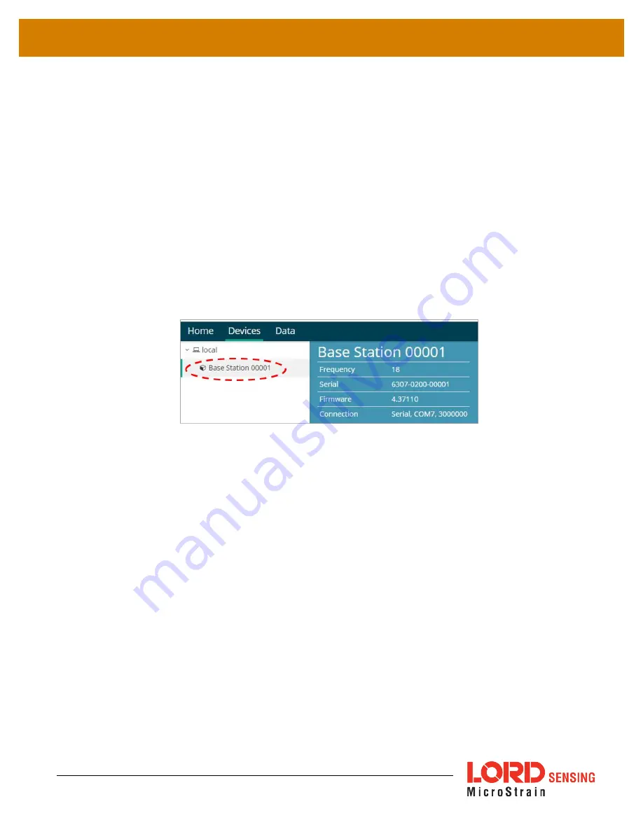
1. Power is applied to the gateway through the USB connection. Verify the gateway status

indicator is illuminated, showing the gateway is connected and powered on.

2. Open the SensorConnect software.

3. The gateway should appear in the Controller window automatically with a communication

port assignment. If the gateway is not automatically discovered, verify the port is active on the

host computer, and then remove and re-insert the USB connector.

Figure 5 - USB Gateway Communication

2.4

Connect to Nodes

Several methods can be used in SensorConnect to establish communication with the nodes: the

automatic node discovery feature, manually entering the node address, and scanning transmission

frequency and node address ranges.

2.4.1

Add A Node Via Node Discovery

For all LORD Sensing 200 Series nodes, a node discovery is triggered by turning on the node. A

discovery packet is sent from the node to all channels and will appear in SensorConnect. The node

address and frequency are indicated in the documentation included with the node when it is

purchased.

10

Summary of Contents for WSDA-200-USB

Page 1: ...LORD USER MANUAL WSDA 200 USB Wireless USB Base Station...

Page 2: ...e Lane Suite 102 Williston VT 05495 United States of America Phone 802 862 6629 Fax 802 863 4093 http www microstrain com sensing_support LORD com sensing_sales LORD com Document 8500 0077 Revision C...

Page 3: ...e Discovery 10 2 4 2 Add A Node Manually 12 2 4 3 Move Node To Base Station Frequency 14 2 5 Configure Node 15 2 6 Sampling Configuration 15 3 Gateway Settings 18 3 1 Transmit Power 18 3 2 Change Freq...

Page 4: ...ns Ports in Windows 31 6 3 Technical Support 33 7 Parts and Configurations 34 7 1 Standard Models 34 7 2 Wireless System Equipment 34 7 3 Product Ordering 34 8 Specifications 35 8 1 Physical Specifica...

Page 5: ...essions between wireless nodes and host computers including continuous sampling burst sampling and datalogging The gateway also facilitates precision sampling synchronization between sensor nodes by t...

Page 6: ...rchased with an internal antenna A or an external antenna B Item Description Product Num ber A WSDA 200 USB Base Station 6307 2040 B WSDA 200 USB Connectivity Cable External Antenna 6307 2140 SensorCo...

Page 7: ...ehavior Figure 2 Status Indicator Behavior Node Status Device Status Indicator OFF Gateway is off ON green Gateway is powered idle Flashing blue Sync sampling beacon enabled or incoming data from othe...

Page 8: ...acquisition from the wireless sensor network This is a PC based software used for configuring gateways and nodes selecting sampling modes and parameters initializing data acquisition and viewing and...

Page 9: ...needed user supplied external a LORD Sensing wireless sensor node a LORD Sensing data gateway and a host computer with access to the data acquisition software The sensor node gateway and software sele...

Page 10: ...f the gateway is not automatically discovered verify the port is active on the host computer and then remove and re insert the USB connector Figure 5 USB Gateway Communication 2 4 Connect to Nodes Sev...

Page 11: ...l pulse once per second to indicate it is in idle mode see Troubleshooting Guide on page 27 If the base and node are on the same operating frequency the node will populate below the Base Station listi...

Page 12: ...cy setting From the Base Station select the Manual Add Node tile enter the Node Address last known Frequency factory default is 15 and select Add Node Figure 8 Add Node By Address If the node was succ...

Page 13: ...indicate the node is not in idle mode or it may be on another frequency If Add Node Anyway is selected it will associate that node with the channel entered but it is likely there will be a communicat...

Page 14: ...number appears next to Base Station the node is operating on a separate radio channel Select the Base Station and then select the Nodes on Other Frequencies tile Figure 11 Nodes On Other Frequencies H...

Page 15: ...iguration 2 6 Sampling Configuration To start a sampling session nodes can be selected individually by selecting the Node name Sampling or as a group by selecting the Base Station Sampling As a group...

Page 16: ...smit a data transmission for each measurement sweep The user should deselect Synchronized if either low latency or the lowest possible power at slow sample rates is required b Lossless The user can ac...

Page 17: ...n data will require fewer transmissions and lower power Selecting Float will request the node send data in the configured calibration unit type g Log Transmit Select Log Only to have the node store al...

Page 18: ...ange between the gateways and nodes NOTE Actual range is highly dependent on how the nodes and gateways are installed and the conditions in the surrounding environment see Range Test on page 26 Settin...

Page 19: ...dinated Universal Time UTC time stamp and it is used to update each node s real time clock RTC This continuous synchronization beacon coupled with the accuracy of the gateway and node clocks 3 ppm dri...

Page 20: ...le gateways on the same frequency To enable and disable the beacon select On or Off from the Toggle Beacon tile A green pop up window will appear confirming the successful action 3 4 Set Nodes to Idle...

Page 21: ...reading This format provides an easy way to organize many sensors and networks and it allows the information to be displayed in the most appropriate layout Figure 18 Viewing Data 4 1 2 Navigating Grap...

Page 22: ...it in the Channels and Settings left sidebar menu Under Channels the channel s for the widget can be enabled and disabled Figure 19 Widget Settings Menu 4 1 4 Time Series Widget Menu The Time Series W...

Page 23: ...ual 4 1 5 Exporting Data Files To export data to a csv file select the Export Data button on the Time Series widget Export name the document save to the preferred location on the host computer Figure...

Page 24: ...sure purchased separately It is designed for desktop use although it can be mounted in any orientation as required by the application It is recommended that it is mounted in a way that optimizes the w...

Page 25: ...ounting Height of the node to allow a clearer LOS path to the gateway Height above the ground is also important because reflections off of the ground can interfere at the receiver Generally the higher...

Page 26: ...re menu and is highly dependent on the physical environment surrounding the devices 1 Select the node name Range Test Figure 23 Range Test Menu 2 RSSI is a measure of signal strength between the node...

Page 27: ...WSDA 200 USB User Manual 6 Troubleshooting 6 1 Troubleshooting Guide 27...

Page 28: ...ode or gateway has no power Verify the node and gateway have power applied and that applicable power switches are on Power is indicated on both devices by a status indicator LED 2 2 gateway has no com...

Page 29: ...e configured In SensorConnect execute the Stop Node command to put the node in idle state allowing configuration to occur 2 8 gateway or node is damaged Verify all connections power and settings If av...

Page 30: ...connections contact LORD Sensing Technical Support See Technical Support on page 33 3 5 sensor channel not configured correctly Verify that the sensor is configured on the correct channel and has been...

Page 31: ...ns port in Windows Windows Device Manage can be used to determine what communication port the gateway is connected to 1 Click on the Windows Start icon and select Control Panel 2 Navigate to the Syste...

Page 32: ...ar on this list with the COM port number The WSDA 200 USB Undefined variable Variables ProductName3 will be displayed as LORD Sensing Virtual COM Port COM 7 If no port is listed the port is not recogn...

Page 33: ...www microstrain com support documentation For further assistance our technical support engineers are available to help with technical and applications questions Technical Support sensing_support LORD...

Page 34: ...ternal antenna 6307 2140 7 2 Wireless System Equipment Model Description LORD Sensing Part Number SensorConnect Software 8220 0023 Table 4 Wireless System Equipment 7 3 Product Ordering Products can b...

Page 35: ...WSDA 200 USB User Manual 8 Specifications 8 1 Physical Specification Dimensions 58 2 mm x 20 3 mm x 10 8 mm Weight 17 grams Enclosure Environmental Rating General purpose indoor 35...

Page 36: ...4 and Proprietary RF transmit power User adjustable from 0 dBm to 20 dBm Power output restricted regionally to operate within legal requirements Power source USB port 5 0 V dc Power consumption 50 mA...

Page 37: ...is subject to the following two conditions 1 This device may not cause interference and 2 This device must accept any interference including interference that may cause undesired operation of the devi...

Page 38: ...g The WSDA 200 USB contains printed circuit boards and electronic components These items are known to contain toxic chemicals and heavy metals that are harmful to humans health and the environment Dis...

Page 39: ...ere to find it Online Wireless Network Calculator http sensorcloud com onlyCalc true SensorConnect Overview Download http www microstrain com software sensorconnect Product Datasheets http www microst...

Page 40: ...g how it is set up for data acquisition It includes settings such as sampling mode rate number of active channels channel measurement settings offsets hardware gain and calibration values Continuous S...

Page 41: ...ving antennas in a radio network As stated it means the antennae are in view of each other with no obstructions LXRS Lossless Extended Range Synchronized is the proprietary LORD Sensing data communica...

Page 42: ...itions producing a predictable electrical signal Sleep a command transmitted to the node to put it into sleep configuration Sampling the process of taking measurements from a sensor or device Sampling...

Page 43: ...ackets second Transmission window the time allowed for one data transmission at the automatically determined transmission rate USB Universal Serial Bus is a serial data communications protocol WSN Wir...

Reviews: