background image

11

3DM

®

-CX5-10 

USER MANUAL

3.5.1 Saving Configurations

Sensor settings are saved temporarily by selecting the OK button in the Device Setup window 

after configuration, but they are lost when the device is powered off. To save current settings, 

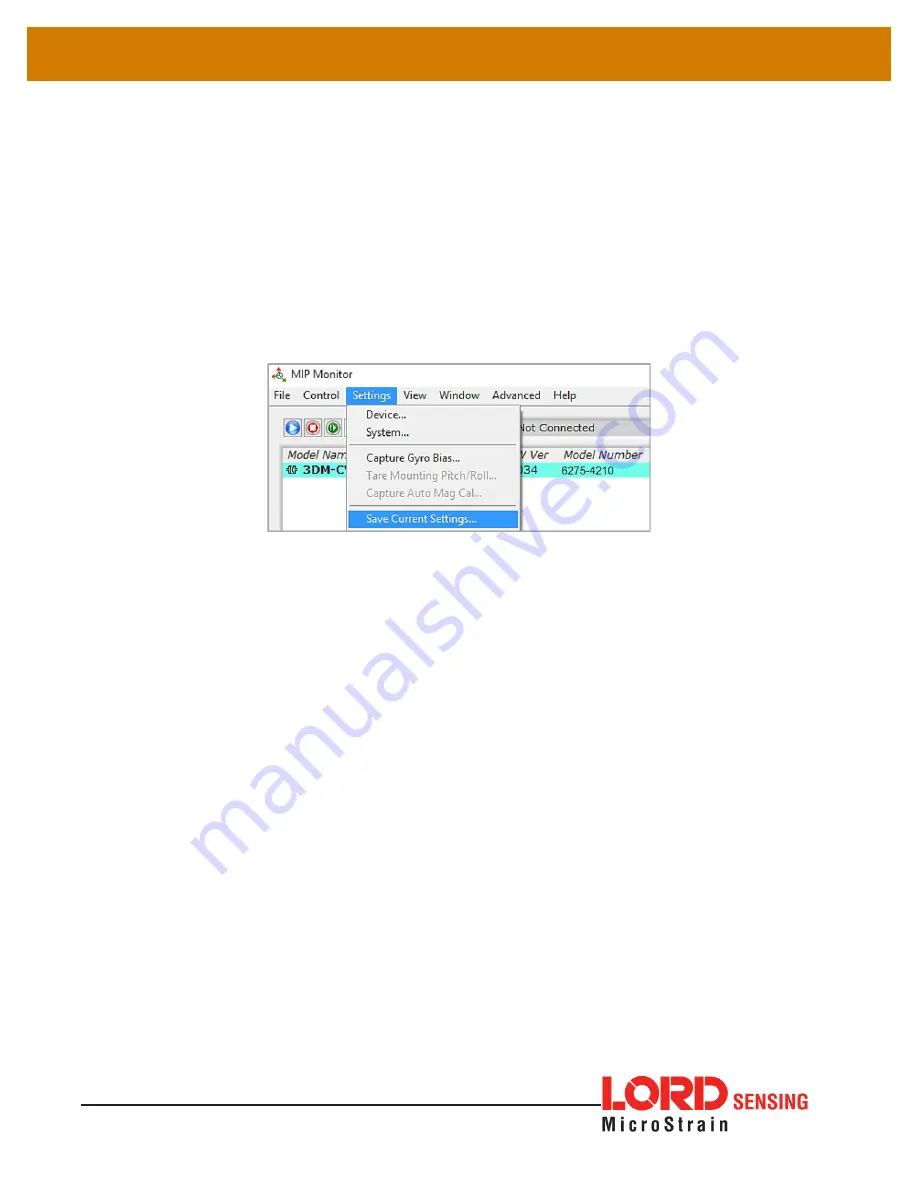
so they are automatically restored the next time the device is powered on, select Settings > 

Save Current Settings.

First adjust the sensor settings to the desired values. Next select Settings > Save Current 

Settings from the main window. The settings will now remain intact when the sensor is 

powered off and then on again.

To recall the last saved settings select Settings > Load Startup Settings. To revert the settings 

back to the factory defaults, select Settings > Load Default Settings.

Figure 10 - Save Sensor Settings

Summary of Contents for 3DM-CX5-10

Page 1: ...LORD USER MANUAL 3DM CX5 10 Inertial Measurement Unit IMU...

Page 2: ...Corporation 3DM 3DM DH 3DM DH3 3DM GX2 Ask Us How DEMOD DC DVRT EmbedSense FAS A G Link Little Sensors Big Ideas LORD Microstrain Live Connect LXRS MathEngine MicroStrain MIP MXRS Node Commander Sens...

Page 3: ...nfigurations 11 3 6 Data Monitoring and Recording 12 3 7 View Recorded Data 14 4 Sensor Measurements 15 4 1 Direct Sensor Measurements IMU Outputs 16 4 2 Sensor Reference Frames 17 4 2 1 Geodetic Fram...

Page 4: ...ireless Adapters 26 8 Troubleshooting 27 8 1 Troubleshooting Guide 27 8 2 Repair and Calibration 30 8 3 Technical Support 30 9 Parts and Configurations 31 9 1 Standard Configurations 31 9 2 Accessorie...

Page 5: ...rovides sensor bias tracking auto zero update options ZUPT and user adjustable sensor noise factors All sensors are fully temperature compensated and calibrated over the full operating temperature ran...

Page 6: ...ion of sensors and environmental compensation allows the 3DM CX5 10 to perform well in a wide variety of applications that require low noise drift gain and offset errors and bias estimation outputs ar...

Page 7: ...additional system products and ordering information see Parts and Configurations on page 31 Item Description Model LORD Sensing Part Number A 3DM CX5 10 Inertial Sensor IMU 8G 300 DPS 6275 4210 MIP Mo...

Page 8: ...n the 3DM CX5 10 include a device status indicator and the device information label The table below describes the basic status indicator behavior includes the sensor frame diagram axis orientation whi...

Page 9: ...IP Data Communications Protocol DCP to write custom software applications with expanded or specific feature sets needed for the application MIP Monitor includes a message building tool that can be use...

Page 10: ...tor software installation menu at https www microstrain com software 2 Download and open the MIP Monitor zip file 3 Run the setup exe file and follow the on screen prompts to completion 4 Download and...

Page 11: ...within the operating range of the sensor or damage or injury could result Once power is applied the sensor is on and active To acquire sensor data the following components are needed 3DM CX5 10 senso...

Page 12: ...includes selections for data sampling recording device settings opening windows selecting which open window to view and advanced features such as selecting the communications mode The icon toolbar inc...

Page 13: ...r in the device list automatically when the software is running The list includes the device information and communication port assignment If the sensor is not automatically discovered use the refresh...

Page 14: ...main window and then select Device Settings or select Settings Device from the main menu For the 3DM CX5 10 these include Main menu tabs The main tabs divide the settings into functional groups for t...

Page 15: ...the next time the device is powered on select Settings Save Current Settings First adjust the sensor settings to the desired values Next select Settings Save Current Settings from the main window The...

Page 16: ...itoring and recording Each view corresponds to one of the main categories in the Device Settings window For example the 3DM CX5 10 includes Sensor Data Monitoring for the IMU AHRS measurements During...

Page 17: ...ed and no data will be recorded even if it is being viewed until data recording is initiated armed In the example below the y axis of the graph indicates data points the x axis is the measurement unit...

Page 18: ...he Arm Recording icon at any time 2 Select the type of data file to generate Binary or CSV The CSV file is the most common and can be viewed and processed by data editors such as Microsoft Excel 3 To...

Page 19: ...l Measurement Unit IMU and include tri axial gyroscopes gyros and tri axial accelerometers This technology provides direct measurements of acceleration angular rate Delta theta change in angular rate...

Page 20: ...asurements or computed measurements Because the sensor system is digital the analog voltage readings from the sensors are converted into a digital equivalent value based on the volt to bit scale of th...

Page 21: ...e standard for cartography and navigation The latest revision WGS84 is the reference coordinate system for GPS It also calculates the magnitude of the local gravity vector using the WGS84 reference fo...

Page 22: ...cted with the true North vector along the line of longitude the East vector along the line of latitude and the Down vector normal to and towards the tangent plane The assumption when using the NED fra...

Page 23: ...e x axis and the z axis goes through the bottom of the sensor outward These axes were selected so that when the connector on the device is pointed north and the device is upright and level the sensor...

Page 24: ...ed Figure 19 Gyro Bias Capture 5 2 Angular Rate and Acceleration Limits The 3DM CX5 10 angular rate and acceleration ranges depend on the sensors installed in the device Exceeding the specified range...

Page 25: ...MU sensor outputs are automatically adjusted for local temperature 5 6 Import and Export Settings The import and export settings features provide a consolidated file of the user settings enabling Devi...

Page 26: ...fastening to ensure maximum stability Mounting fasteners should be 2 56 x button head screws either brass or 300 series stainless steel The sensor can be mounted in any orientation as required for th...

Page 27: ...ent and received as fields in a message packet The packets have a descriptor type field based on their contents so it is easy to identify if a packet contains commands replies or data To view or downl...

Page 28: ...nsor damage could result There are two input power pins available connect only one at a time Sensor power and serial communications cables are available from LORD Sensing and come with the sensor deve...

Page 29: ...ing data as soon as it powered on This can be useful in sensor integration applications in which immediate data acquisition is desired and connection to MIP Monitor for data logging is not required Th...

Page 30: ...distribute sensor outputs For more information and examples refer to the Using Dataloggers with Inertial Sensors Technical Note on the LORD Sensing website or contact LORD Sensing Technical Support 7...

Page 31: ...27 3DM CX5 10 USER MANUAL 8 Troubleshooting 8 1 Troubleshooting Guide...

Page 32: ...COMMUNICATION no communication to sensor 2 1 sensor not found in MIP Monitor In MIP Monitor use the Refresh button to look for the sensor again If the sensor is still not found try cycling power to t...

Page 33: ...reaming data activate it in the software 3 3 sensor data not recorded Verify data recording has been activated In MIP Monitor the device status information field will indicate Recording Data If the se...

Page 34: ...al date of purchase LORD Sensing will repair or replace at its discretion a defective product if returned to LORD Sensing within the warranty period This warranty does not extend to any LORD Sensing p...

Page 35: ...or contact the LORD Sensing Sales Department Table 3 Model Numbers describes the standard models available at the time this manual was published Once a model is selected the part number is further de...

Page 36: ...MANUAL The same options are available in each model and are indicated in the last four digits of the product part number For a list of the starter kit contents see Components on page 3 Figure 25 Stan...

Page 37: ...r RS232 development kit 6212 3010 Table 4 Sensor Accessories 9 3 Sales Support Products can be ordered directly from the LORD Sensing website by navigating to the product page and using the Buy featur...

Page 38: ...Resolution 0 02 mg 8 g 0 003 sec 300 degrees second Bias instability 0 04 mg 8 hr Initial bias error 0 002 g 0 04 sec Scale factor stability 0 03 0 05 Noise density 25 g Hz 2 g 0 005 sec Hz 300 sec A...

Page 39: ...ange 5000 g survivability Physical Specifications Dimensions 38 mm x 24 mm x 9 7 mm Weight 11 grams Enclosure material Aluminum Regulatory compliance ROHS CE Integration Connectors Data power output m...

Page 40: ...ed diagrams notes and references on the 3DM CX5 family of inertial sensors Figure 26 3DM CX5 Sensor 10 2 3DM CX5 Development Kit See the 3DM CX5 Reference Design Documentation for detailed drawings an...

Page 41: ...se documents are continuously updated and may provide more accurate information than printed or file copies Document Where to find it 3DM CX5 10 support documentation http www microstrain com document...

Page 42: ...derate injury to workers and or the general public Situations where a non immediate or potential hazard presents a risk to damage of property and equipment May be used to indicate important operationa...

Reviews: