background image

4


Safety Precautions 

© Travis Industries 

12/27/2018 - 1440 

Berkshire GSR2 3-Sided 

  Failure to follow all of the requirements may result in property damage, bodily injury, or even death. 

Young children should be carefully supervised when they are in the same room 
as the appliance.  Toddlers, young children and others may be susceptible to 
accidental contact burns.  A physical barrier is recommended if there are at risk 
individuals in the house.  To restrict access to a fireplace or stove, install an 
adjustable safety gate to keep toddlers, young children and other at risk 
individuals out of the room and away from hot surfaces. 


Children and adults should be alerted to the hazards of high surface temperature 
and should stay away to avoid burns or clothing ignition.  Do not touch the hot 
surfaces of the heater.  Educate all children of the danger of a high-temperature 
heater.   


Due to the high temperature, the heater should be located out of traffic and away 
from furniture and draperies. 

  This unit must be installed by a qualified installer to prevent the possibility of an explosion.  

  This appliance must be installed in accordance with all local codes, if any; if not, in U.S.A. follow ANSI 

Z223.1 and NFPA 54(88), in Canada follow CSA B149.1. In Australia follow AS/NZS 5601.1. 

  A manufactured home (USA only) or mobile home OEM installation must conform with the 

Manufactured Home Construction and Safety Standard, Title 24 CFR, Part 3280, or, when such a 
standard is not applicable, the Standard for Manufactured Home Installations, ANSI/NCSBCS 
A225.1, or Standard for Gas Equipped Recreational Vehicles and Mobile Housing, CSA Z240.4.  This 
appliance may be installed in Manufactured Housing only after the home is site located. 

  All exhaust gases must be vented outside the structure of the living-area.  Combustion air is drawn 

from outside the living-area structure.  The venting must not be connected to a chimney flue serving a 
separate solid-fuel burning appliance. 

  Notify your insurance company before hooking up this fireplace.   

  The instructions in this manual must be strictly adhered to.  Do not use makeshift methods or 

compromise in the installation.  Improper installation will void the warranty and safety listing. 

  This heater is approved for use with natural gas (NG) or propane (LP).  Burning the incorrect fuel will 

void the warranty and safety listing and may cause an extreme safety hazard.  Direct questions about 
the type of fuel used to your dealer. 

  Contact your local building officials to obtain a permit and information on any installation restrictions 

or inspection requirements in your area.   

  If the flame becomes sooty, dark orange in color, or extremely tall, do not operate the heater.  Call 

your dealer and arrange for proper servicing. 

  It is imperative that control compartments, screens, or circulating air passageways of the heater be 

kept clean and free of obstructions.  These areas provide the air necessary for safe operation. 

  Do not operate the heater if it is not operating properly in any fashion or if you are uncertain.  Call 

your dealer for a full explanation of your heater and what to expect. 

  Do not store or use gasoline or other flammable liquids in the vicinity of this heater. 

  Do not operate if any portion of the heater was submerged in water or if any corrosion occurs.  

Immediately call a qualified service technician to inspect the appliance and to replace any part of the 
control system and any gas control which has been under water. 


Summary of Contents for Berkshire GSR2 Deluxe

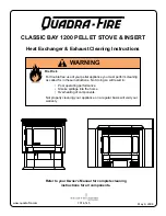
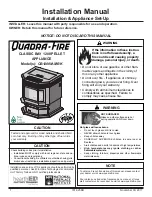
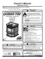
Page 1: ...S UNTIL COOLED NEVER ALLOW CHILDREN TO TOUCH GLASS A barrier designed to reduce the risk of burns from the hot viewing glass is provided with this appliance and shall be installed for the protection of children and other at risk individuals Tested and Listed by ANSI Z21 88 2014 CSA 2 33 2014 Direct Vent Stove Natural Gas or Propane Residential or Mobile Home This appliance may be installed in an a...

Page 2: ...um benefit and enjoyment from your heater Important Information No other Berkshire Stove has the same serial number as yours The serial number is on the listing plate chained to the gas control valve This serial number will be needed in case you require service of any type Model Lopi Berkshire GSR2 Stove_ Serial Number Purchase Date Purchased From Register your warranty online at traviswarranty co...

Page 3: ...og Placement 28 Right Twig Placement 28 Right Front Log Placement 29 Left Cross Log Placement 29 Right Cross Log Placement 30 Left Twig Placement 30 Center Twig Placement 31 Ember Placement 32 Rockwool Installation 32 Before You Begin 33 Remote Set Up 34 Verify the Switch is on REMOTE 34 Synchronize the Transmitter to the IFC 34 Location of Controls 35 Direct Operation 35 Starting the Stove for th...

Page 4: ...s appliance may be installed in Manufactured Housing only after the home is site located All exhaust gases must be vented outside the structure of the living area Combustion air is drawn from outside the living area structure The venting must not be connected to a chimney flue serving a separate solid fuel burning appliance Notify your insurance company before hooking up this fireplace The instruc...

Page 5: ...ff valve is usually next to the gas meter or propane tank and requires a wrench to shut off A barrier designed to reduce the risk of burns from the hot viewing glass is provided with this appliance and shall be installed for the protection of children and other at risk individuals If the barrier becomes damaged the barrier shall be replaced with the manufacturer s barrier for this appliance Clothi...

Page 6: ...uare feet 500 1 500 Maximum Input 31 000 BTU s Heating capacity will vary depending on the home s floor plan degree of insulation and the outside temperature Dimensions Weight Electrical Specifications for optional blower Electrical Rating 115 Volts 1 5 Amps 60 Hz 180 watt typical max amps 5 Fuel This heater is shipped in natural gas NG configuration but may be converted to propane LP using the in...

Page 7: ...This appliance may be installed in Manufactured Housing only after the home is site located This stove is designed to operate on natural gas or propane LP All exhaust gases must be vented outside the structure of the living area Combustion air is drawn from outside the living area structure Notify your insurance company before hooking up this stove The requirements listed below are divided into se...

Page 8: ... smoke from the paint curing and oil burning off the steel may occur the first time you start this heater This is normal We recommend you open windows to vent the room Stove Clearances Mobile Home Requirements When the stove is installed in a mobile home it must be bolted to the floor and the appliance grounded use the optional blower with a grounded circuit or other suitable grounding method curr...

Page 9: ...st not be placed so the vents below or above the door along the sides of heater or along the back of the heater can become blocked This heater may be placed in a bedroom Please be aware of the large amount of heat this appliance produces when determining a location Floor Protection Requirements When the stove is installed directly on carpeting vinyl or other combustible material other than wood fl...

Page 10: ... inlet is shown below A manual shutoff valve is required for installation it must be located within 3 915mm of the heater T Handle gas cocks are required in Massachusetts in compliance with code 248CMR This stove is shipped with a 24 610 long 3 8 10mm diameter flex gas line attached to an elbow on the gas control valve see illustration below for location The flex gas line accepts a 3 8 flare fitti...

Page 11: ...e restrictor settings detailed in the manual should be followed variations may occur depending upon installation parameters Many factors may negatively influence the draft of the appliance Travis Industries will not be responsible for improper draft due to factors such as trees hills buildings obstructions excessive wind extreme hot or cold outdoor temperatures restrictive vent terminations or inf...

Page 12: ...wever three screws may be used to secure vent sections together if desired High temperature sealant is recommended at the appliance starter section connection use high temperature silicone or Mill Pac If disassembly is required at time of re assembly check to see if the vent creates a tight fit If it does not apply high temperature sealant to the joints of the affected sections Horizontal sections...

Page 13: ... and place it aside To Adjust the Restrictor To Access the Restrictor NOTE The restrictor is shipped in position 1 This restrictor is in position 6 Lift the cotter pin out a Slide the restrictor adjustment rod in b Replace the cotter pin through the correct hole on the restrictor adjustment rod c Restrictor Positions 2 4 6 3 5 1 Vent Horizontal Run Vent Horizontal Run is measured from the start of...

Page 14: ... position 5 feet 1 5m 10 feet 3m 15 feet 4 5m 20 feet 6m 25 feet 7 5m 30 feet 9m 0 feet 40 max 12m 5 feet 1 5m 0 feet 0 feet 5 feet 1 5m 10 feet 3m 15 feet 4 5m 20 feet 6m 25 feet 7 5m 30 feet 9m 40 max 12m Restrictor Position 5 NOTE Restrictor positions are based upon lab tests The ideal restrictor position may vary slightly especially when the termination is near a demarkation line Restrictor Po...

Page 15: ... the chart Use the indicated restrictor position 5 feet 1 5m 10 feet 3m 15 feet 4 5m 19 max 5 8m 0 feet 5 feet 1 5m 0 feet 0 feet 5 feet 1 5m 10 feet 3m 15 feet 4 5m Restrictor Position 5 NOTE Restrictor positions are based upon lab tests The ideal restrictor position may vary slightly especially when the termination is near a demarkation line Restrictor Position 1 10 feet 3m 15 feet 4 5m 20 feet ...

Page 16: ... within the shaded area shown in the chart Use the indicated restrictor position 5 feet 1 5m 10 feet 3m 15 feet 4 5m 19 max 5 8m 0 feet 5 feet 1 5m 0 feet 0 feet 5 feet 1 5m 10 feet 3m 15 feet 4 5m Restrictor Position 5 NOTE Restrictor positions are based upon lab tests The ideal restrictor position may vary slightly especially when the termination is near a demarkation line Restrictor Position 1 ...

Page 17: ...r position 5 feet 1 5m 10 min 3m 15 feet 4 5m 21 max 6 4m 0 feet 5 feet 1 5m 0 feet 0 feet 5 feet 1 5m 10 min 3m 15 feet 4 5m Restrictor Position 5 NOTE Restrictor positions are based upon lab tests The ideal restrictor position may vary slightly especially when the termination is near a demarkation line Restrictor Position 1 10 feet 3m 15 feet 4 5m 20 feet 6m 24 max 7 3m 0 feet 5 feet 1 5m 10 fee...

Page 18: ...5 feet 4 5m 20 feet 6m 25 feet 7 5m 30 feet 9m 40 max 12m Restrictor Position 5 NOTE Restrictor positions are based upon lab tests The ideal restrictor position may vary slightly especially when the termination is near a demarkation line Restrictor Position 6 10 feet 3m 15 feet 4 5m 20 feet 6m 24 max 7 3m 0 feet 5 feet 1 5m 10 feet 3m 15 feet 4 5m 20 feet 6m 24 max 7 3m 35 feet 10 5m 35 feet 10 5m...

Page 19: ...5 feet 7 5m 30 feet 9m 0 feet 40 max 12m 5 feet 1 5m 0 feet 0 feet 5 feet 1 5m 10 feet 3m 15 feet 4 5m 20 feet 6m 25 feet 7 5m 30 feet 9m 40 max 12m Restrictor Position 5 NOTE Restrictor positions are based upon lab tests The ideal restrictor position may vary slightly especially when the termination is near a demarkation line 10 feet 3m 15 feet 4 5m 20 feet 6m 24 max 7 3m 0 feet 5 feet 1 5m 10 fe...

Page 20: ...odes and the requirements of the gas supplier G Minimum 48 1219mm clearance from any adjacent building H Minimum 84 2134mm clearance above any grade when adjacent to public walkways or driveways NOTE may not be used over a walkway or driveway shared by an adjacent building I Minimum 9 229mm clearance to any non mechanical air supply inlet to the building or the combustion air inlet to any other ap...

Page 21: ... Metalbestos 6 I D Security Chimneys 6 I D Jackes Evans 6 I D Hart Cooley 6 I D Pro Jet 6 I D Chimney Conversion Kit B 932 Simpson Dura Vent 6 I D Air Jet 6 I D Metal Fab 6 and 7 I D Amer Metals 6 7 I D Metalbestos 7 and 8 I D Jackes Evans 7 and 8 I D Hart Cooley 7 and 8 I D Pro Jet 7 and 8 I D Security Chimneys 8 I D Chimney Conversion Kit C 933 Simpson Dura Vent 7 and 8 I D American Metals 8 I D...

Page 22: ...spect the chimney 711 Flex Liner 4 dia or other UL 1777 Gas Liner Co Axial Straight Lengths 991 High Wind Termination 990 90 Elbow Flashing included in 934 Masonry Conversion Kit Make sure the coaxial pipe maintains a 1 clearance to any combustible The vent must be sealed air tight High Temp Silicone Connector with Cover included in 934 Masonry Conversion Kit Interior Masonry Chimney Standard Maso...

Page 23: ... firebox ensuring gas does not build up 3 Make sure the accent light bulb is in place NOTE Take care to not touch the bulb with your fingers use a cloth or paper towel 4 Install the four AA batteries into the battery holder see illustration below The AA batteries act as a power backup in case the household AC power goes out and are required for operation Install three AAA batteries into the remote...

Page 24: ...he flames should not contact the top of the firebox Check the flame on low position The flames should burn off of each burner hole If the heater does not work correctly contact your Travis dealer for a remedy 11 Give this manual to the home owner for future reference and fully explain operation of this heater Correct Flames should be blue at the base yellow orange on the top If the flames are too ...

Page 25: ...al tabs on the stove front slide over the tabs on the side castings Lift the stove top off the stove and place it aside a Re Attaching the Glass Frame a Slide the two brackets on the bottom of the glass frame into the glass frame guides hold the glass frame at a slight angle b Swing the glass frame into place you may have to lift it slightly to allow it to fit over the top of the firebox c Attach ...

Page 26: ...it is turned 1 4 turn when it is disengaged Follow the directions below to re install the latch if it becomes loose Top of Firebox Hold the latch at an angle and insert it into the slot on the glass frame anchor NOTE this slot may be at a different angle than illustrated Note how the washer on the latch fits behind the flange on the glass frame anchor Glass Frame Anchor Once fully inserted turn th...

Page 27: ...y parts specifically approved with this appliance may result in property damage or personal injury If using propane LP convert the appliance before installing the logs see page 49 The burner must be correctly positioned before installing the logs Make sure the burner is fully seated and the pilot is properly aligned See page 49 for details on burner removal Rear Log Placement The rear log has two ...

Page 28: ...ent The left front log has two holes on the bottom Place the log so the pin on the burner and the metal bracket insert into the holes on the log see photos below Right Twig Placement Place the right twig on the burner as shown below Make sure it does not cover any burner holes NOTE On LP push the log to the back On NG pull the log forward ...

Page 29: ...log has two holes on the bottom Place the log so both burner pins insert into the holes on the log see photos below Make sure the log is pushed back so it sits flat Left Cross Log Placement Place left cross log as shown below Note how the log rests on the flat spots of the back and left logs NOTE On LP push the log to the back On NG pull the log forward ...

Page 30: ...7 2018 1440 Berkshire GSR2 3 Sided Right Cross Log Placement Place the log as shown below The right cross log rests on the flat spots of the rear and the right front logs Left Twig Placement Place the left twig on the burner as shown below Make sure it does not cover any burner holes ...

Page 31: ...ied installers only 31 Travis Industries 12 27 2018 1440 Berkshire GSR2 3 Sided Center Twig Placement Place the center twig on the burner as shown below Make sure it does not cover any burner holes The completed installation is shown below ...

Page 32: ...hance the glow from the burner The rock wool works best when it is applied in a very thin porous layer The best method for applying the rock wool is to brush it on to the burner Compress a clump of rockwool between your thumb and forefinger Use a stiff brush to apply a thin layer of rockwool fibers onto the burner Do not use the entire bag of rockwool Use only a small amount and save the remainder...

Page 33: ...he modes flame height blower light comfort control Standing Pilot or auxiliary power input This allows you to tailor the remote to the appliance We do not recommend disabling the standing pilot option for our gas appliances This feature may be recommended for cold regions or installations with sub optimal venting How to Disable Enable the Thermostat The remote is shipped with the thermostat enable...

Page 34: ...IFC The transmitter will need to be synchronized to the IFC Integrated Fireplace Control before the remote will work correctly Synchronizing is done in the following two steps below see illustration below 1 Press the PRG Program button on the battery box IFC will beep 3 times 2 Press the ON button on the transmitter IFC will beep 3 times NOTE If power is cut off to the IFC for an extended period o...

Page 35: ...smitter NOTE When the battery holder switch is turned to ON or OFF the mode settings Flame Height Comfort Control will remain in the same state as before the switch was moved i e the IFC remembers the last setting If you wish to adjust the mode settings use the transmitter mode button to adjust the settings see Mode Controls on page 39 The thermostat and burner on off operating functions will not ...

Page 36: ...mes lift off the burner If this is situation we recommend you switch to continuous pilot This will create a slight draft in the vent allowing for the burner to light quickly and draft correctly Excessive Condensation on Glass After Startup certain installations may encounter excessive fogging on the window after startup not just the first time the heater was started This is an aesthetic condition ...

Page 37: ...ctions see illustration below Listen for the Beep Each time you press a button on the transmitter that controls the fireplace a beep will come from the IFC When you change thermostat target settings the IFC will not beep NOTE When the batteries start to get low the IFC will beep twice whenever a button is pressed When the batteries are nearly depleted the IFC will no longer beep See IFC Batteries ...

Page 38: ...ure is achieved STANDARD THERMOSTAT While in standard thermostat setting the transmitter will turn the burner on and off to achieve the target temperature see illustration below To adjust the target temperature press the up and down buttons until a suitable temperature is achieved NOTE If the transmitter batteries go dead while in thermostat setting standard or smart the appliance will shut off af...

Page 39: ... The center display will display the 7 settings from OFF to HI for full on MANUAL MODE BLOWER OPERATION When in Manual Mode the blower will remain on even if the burner is turned off and the heater cools Either manually turn the blower off or turn off the heater by pressing the On Off button F Flame Height OFF Look here for mode controls Press the mode button to cycle through the mode settings Opt...

Page 40: ...urner may be turned on and off using the up and down buttons when in Comfort Control Mode see illustration below The center display will display either ON or OFF Display Fahrenheit or Celsius With the system in the OFF position press both the MODE and THERMOSTAT buttons simultaneously to toggle between Fahrenheit F and Celsius C F OFF MAX When in accent light mode this icon will appear darkened Th...

Page 41: ...on page 41 In applications where the appliance is required to provide heat we recommend replacing the batteries before each heating season Battery Replacement Battery Installation Install four AA batteries into the battery holder see illustration below These batteries act as a power backup in case the household AC current goes out Transmitter Battery Installation Install the three included AAA bat...

Page 42: ...al during start up You may notice the smell is more acute if the appliance was left idle for a long period MAX F OFF Child Proof Indicator Gas Control Valve As the gas control valve is turned on and off you will hear a dull clicking sound This is the valve opening up and shutting down The appliance may creak with change of temperature THIS IS NORMAL Pilot Flame The pilot flame will make a clicking...

Page 43: ... portions of the finish may become slightly dull in appearance especially over the top where it becomes hot This is normal The only cleaning we recommend is a light dusting when the appliance is cool DO NOT USE ANY LIQUID CLEANER OR ABRASIVES ON THIS FINISH Front Glass Clean the glass with soap and water do not use abrasive cleaners Glass removal instructions are on page 25 Side Glass The interior...

Page 44: ...ss door clean if necessary Check the gas control valve and the gas lines If damage is found discontinue use and contact your dealer for service Clean the air channels ducts and blower if applicable Inspect vent and vent termination for sooting obstructions or damage Make repairs as needed Remove any debris or vegetation near the vent termination Contact your dealer if any sooting or deterioration ...

Page 45: ...es Replace the fuse See fuse location below Stove Will Not Distribute Heat The stove is not getting electricity The stove is not up to temperature Check the breaker switch Let the stove burn for at least 15 minutes Flames Are Too Blue The stove has just been started Improper air shutter adjustment This is normal see Starting the Stove for the First Time Adjust Air Shutter contact your dealer Flame...

Page 46: ...stem Jumper Purple Grey Pilot Sensor Spark Rod Comfort Control Valve Battery Box Manual On Off Accent Light s 3 Amp Fuse Optional Blower s 3 Amp Fuse Appliance Ground Accessory Power Appliance Ground Green Orange Yellow Green White Blue IPI CPI JUMPER WIRE Blue Pink Power In TOP 4 AA Batteries Black Red Yellow Orange Yellow Flame Detect Black Red Purple Grey Black White Green Integrated Fireplace ...

Page 47: ... system to vent this appliance to the exterior See owner s manual for approved brands of venting If the vent air intake system is disconnected for servicing or any other reason it must be resealed and or reinstalled WARNING Improper installation adjustment alteration service or maintenance can cause injury or property damage Refer to the owner s information manual provided with this appliance For ...

Page 48: ...e damage incurred while the appliance is in transit alteration or act of God 8 This 7 Year warranty excludes damage caused by normal wear and tear such as paint discoloration or chipping worn or torn gasketing corroded or cracked logs embers etc Also excluded is damage to the unit caused by abuse improper installation modification of the unit drilling of the orifices or the use of fuel other than ...

Page 49: ...ry or loss of life The qualified service agency is responsible for the proper installation of this kit The installation is not proper and complete until the operation of the converted appliance is checked as specified in the manufacturer s instructions supplied with the kit CAUTION The gas supply shall be shut off prior to disconnecting the electrical power before proceeding with the conversion IM...

Page 50: ...e burner orifices see below Replace the manifold cover after the LP burner orifices are installed 4 Follow the directions below to replace the orifices ORIFICE SIZE Natural Gas LP Propane Front Burner Orifice 50 DMS 58 DMS Rear Burner Orifice 47 DMS 56 DMS Front Burner Orifice a Rear Burner Orifice c 15 16 24mm b Orifice ID Thread Sealant 1 2 Wrench ...

Page 51: ...ifice following the directions below a Use a 7 16 open end wrench to remove the pilot hood b Remove and discard the Natural Gas NG orifice Place the LP orifice in the pilot assembly then replace the pilot hood tightening the pilot hood until it is snug do not over tighten 7 Replace the firebox components Install the logs and embers Replace the glass NG Air Deflector LP Air Deflector a b 7 16 Wrenc...

Page 52: ...ith it make sure to follow all of the directions Place the stepper motor on the gas control valve see pictures below MAKE SURE IT IS CORRECTLY ORIENTED Secure using the screws included with the motor tighten to 25 Lb inches Leak test this area after installation to verify proper installation 9 Make the gas line connection bleed the gas line if applicable start the heater and thoroughly leak test a...

Page 53: ...Optional Equipment for qualified installers only 53 Travis Industries 12 27 2018 1440 Berkshire GSR2 3 Sided ...

Page 54: ...or Masonry Chimney Conversions 22 Intermittent Continuous Pilot 36 Introduction 2 Listing Details 2 Location of Controls 35 Log Installation 27 Low Battery Indicator 41 LP Conversion Instructions 49 Maintaining Your Stove s Appearance 43 Mobile Home Requirements 8 Normal Operating Odors 42 Normal Operating Sounds 42 Packing List 7 Power Outages 41 Remote Control Warnings 33 Remote Operation 37 Rem...

Reviews: